5 Place an “in service” date” on Battery 1 and Battery 2.
Do not connect the two batteries in parallel. A parallel connection will not provide the 24 volts required for
operating the Sigma A-CP Fire Control Panel in a standby condition.
The recharging circuit of the power supply charges batteries to a maximum voltage of 27.6 VDC @
1.7 A. The fire control panel accepts 7 AH or 12 AH, valve-regulated, lead-acid, rechargeable-batteries.
The maximum current drawn from the batteries is 5.18 Amps when the main AC power source is
disconnected. Observe polarity when connecting the leads of the standby-batteries to the fire control
panel. Improper connections to the standby-batteries could damage the fire control panel and
severely limit overall fire control panel operation. Connect two standby-batteries to the power supply
in series. Do not connect the two batteries in parallel. A parallel connection will not provide the 24
volts required for operating the Sigma A-CP Fire Control Panel.
Reference Section 5, Maintenance for replacing the standby-batteries.
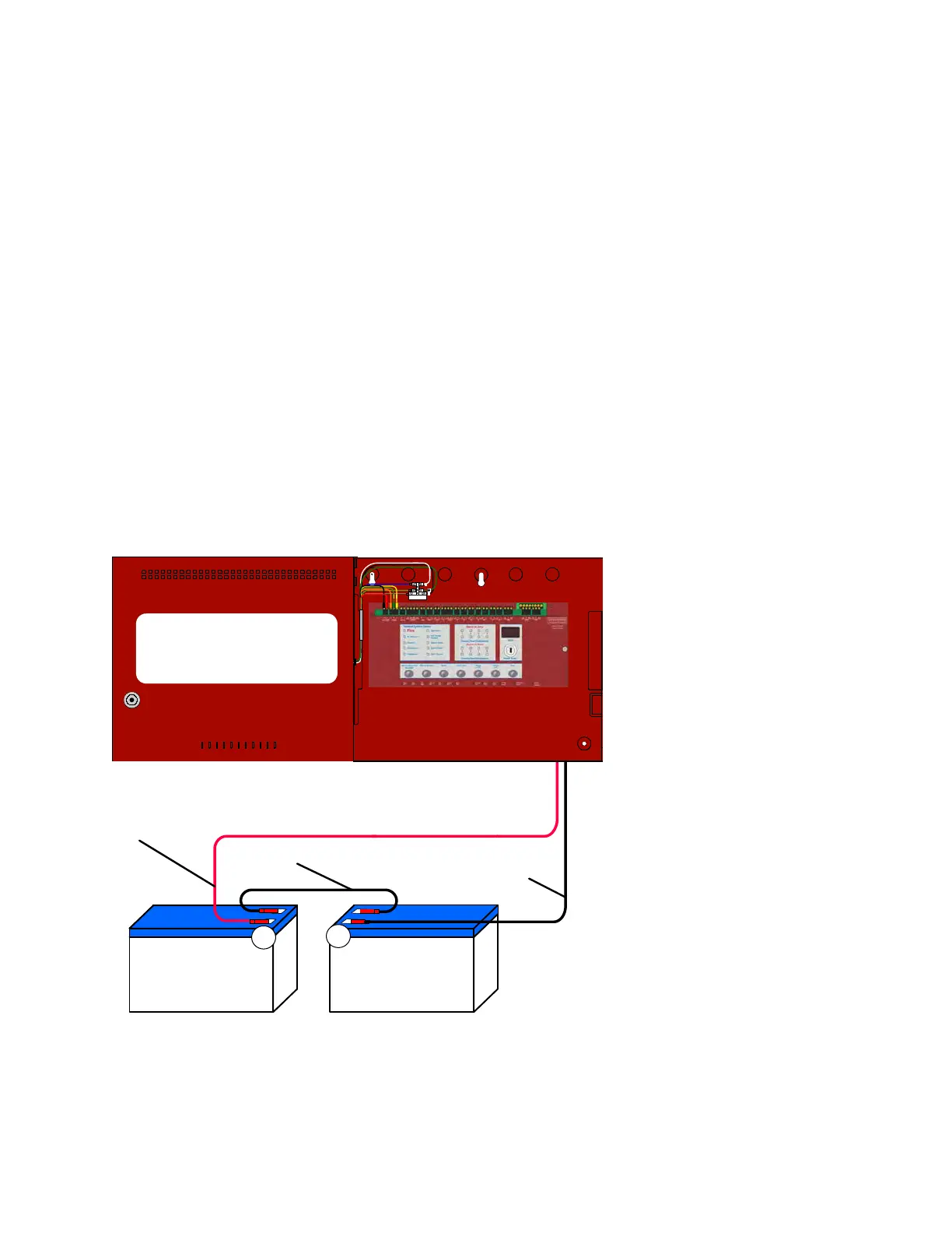
The figure below illustrates standby-battery connections on the Sigma A-CP Fire Control Panel:
Figure 3- 5
Standby-Battery Connections
Negative Battery Lead
( Black Cable )
Jumper-Lead
12 AH Battery
Positive Battery Lead
( Red Cable )
Each standby-battery is 12 VDC, 12 AH and sealed-rechargeable
-
+
L
N
FUSE
12 AH Battery
The series connection illustrated provides a standby voltage of 24 VDC required by the Sigma A-CP Fire
Control Panel.
www.acornfiresecurity.com
www.acornfiresecurity.com