33 o f 105
Installation 3
Sigma A-CP Fire Control Panel - Installation and Operation Manual
Man-1194 (K1861-00), Revision E01.04
3
Press the Optional Dialer Board against the Main Board to complete the connection.
The connection is complete when connector J2 of the Optional Dialer Board inserts in connector J1 of the
Main Board.
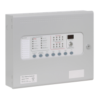
4 Secure the Optional Dialer Board to the Main Board with four standoff-screws.
The figure below illustrates the secured location of the Optional Dialer Board on the Main Board:
Figure 3- 10
Optional Dialer Board and the Main Board
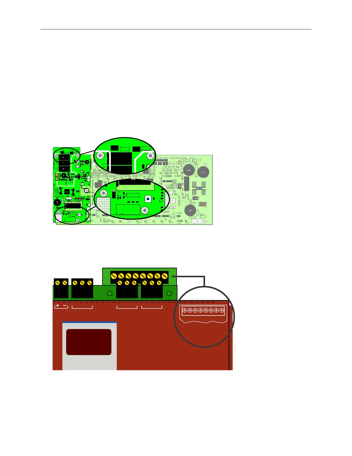
The figure below illustrates field terminals of the Optional Dialer Board:
Figure 3- 11
Field Terminals of the Optional Dialer Board
Reference Appendix B, Equipment List for Sigma A-CP Fire Control Panel models supporting the Optional
Dialer Board. Reference Appendix A, Specifications for wire gages acceptable for these terminal block
connections.
TV2
TV3
K2
TV2
K1
D3
J
SW1
J1
Mode
Z8 TRBL SUPV . FIRE
NC C NONC C NONC C NO
L1T L1R P1T P1R L2T L2R P2T P2R
DIALER BOARD
CONNECTIONS
www.acornfiresecurity.com
www.acornfiresecurity.com