Installation
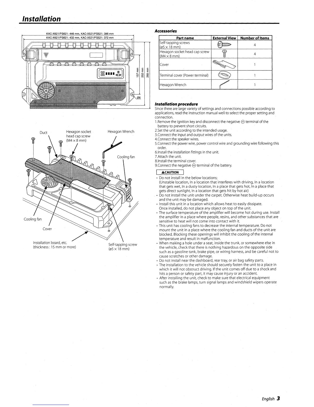
Part name
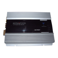
External View Number
of
Items
Self-tapping
screws
@)mn>
4
0S
x
18
mm)
Hexagon
socket
head
cap
screw
f
4
M4x8mm)
Cover
~
1
Terminal
cover
(Power
terminal)
@
1
Hexagon
Wrench
~
1
•
Do
not install
in
the below locations;
(Unstable
location,
In
a location that interferes with driving,
In
a location
that
gets
wet,
In
adusty location,
In
a
place
that
gets
hot,
In
a
place
that
gets
direct sunlight,
In
a location that
gets
hit
by
hot
air)
•
Do
not install the unit under the
carpet.
Otherwise
heat
build-up
occurs
and
the unit
may
be
damaged.
•
Install
this unit
in
a location which allows heat to
easily
dissipate.
Once
installed, do not
place
any
object
on
top of the unit.
•
The
surface
temperature of the amplifier will become hot during
use.
Install
the amplifier
in
a
place
where people,
resins,
and
other
substances
that
are
sensitive
to
heat
will not come into contact with
it.
•
This
unit
has
cooling
fans
to
decrease
the internal temperature.
Do
not
mount the unit
in
a
place
where the cooling
fan
and
ducts ofthe unit
are
blocked. Blocking
these
openings will inhibit the cooling
of
the internal
temperature
and
result
in
malfunction.
•
When
making ahole under a
seat,
inside the trunk,
or
somewhere
else
in
the vehicle,
check
that there
is
nothing
hazardous
on
the opposite
side
such
as
agasoline
tank,
brake
pipe,
or
wiring
harness,
and
be
careful
not
to
cause
scratches
or
other
damage.
•
Do
not install
near
the dashboard,
rear
tray,
or
air
bag
safety
parts.
•
The
installation
to
the vehicle should
securely
fasten
the unit to a
place
in
which it will not obstruct driving. If the unit
comes
off
duE'
to a
shock
and
hits a
person
or
safety
part, it
may
cause
injury
or
an
accident.
• After installing the unit,
check
to
make
sure
that electrical equipment
such
as
the
brake
lamps,
turn
signal
lamps
and
windshield wipers operate
normally.
Instal/ationprocedure
Since
there
are
large
variety
of
settings
and
connections
possible
according to
applications,
read
the
instruction
manual
well
to
select
the proper setting
and
connection.
1.Remove
the ignition
key
and
disconnect the
negative
8 terminal ofthe
battery to
prevent
short
circuits.
2.Set
the unit
according
to
the
intended
usage.
3.Connect
the
input
and
output
wires
ofthe
units.
4.Connect
the
speaker
wires.
5.Connect
the
power
wire,
power control
wire
and
grounding
wire
following this
order.
6.lnstall
the
installation fittings
in
the
unit.
7.Attach
the
unit.
8.lnstall
the terminal
cover.
9.Connect
the
negative
8 terminal of
the
battery.
ACAUTION
Accessories
E E
E E
~
re
Self-tapping
screw
(05
x
18
mm)
Hexagon
Wrench
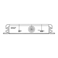
Duct
Installation
board,
etc.
(thickness:
15
mm
or
more)
English
3