Do you have a question about the Kenwood KR-5030 and is the answer not in the manual?
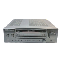
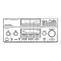
Identifies meters, dial, knobs, and rings on the front.
Details rear jacks, AC outlet, terminal board, and switch.
Covers AM bar antenna and power cord.
Describes the feet for unit stability.
Illustrates the placement of major internal sections.
Step-by-step instructions for dial cord installation.
Steps for removing pilot lamp board and power supply.
Instructions for removing the main panel and rear panel.
Guide for detaching the tuner PC board.
Steps for removing power transistor block and amp PC board.
Instructions for removing the meter and tuner PC board.
Guide for removing the pilot lamp for dial calibrations.
Block diagram of FM/AM signal paths.
Diagrams of audio, protection, and control circuits.
Graphs illustrating signal levels at various stages.
Explains the Active Service Optimization circuit.
Describes the DC detection and relay protection mechanism.
Details the functionality of the AM muting circuit.
Explains the FM tuning and detuning operational circuits.
Describes FM mono operation and delay circuit functions.
Covers adjustments for FM reception stages.
Details adjustments for the AM tuner stages.
Outlines bias and volume adjustments for audio.
Lists maximum operating parameters for transistors and FETs.
Details for audio, RF, and multiplex signal generators.
Specs for voltmeters, counters, and distortion meters.
Power output, distortion, frequency response, and sensitivity.
Usable sensitivity, quieting, and signal-to-noise ratios.
AM sensitivity, selectivity, dimensions, and weight.
| Input Sensitivity | 2.5mV (MM), 150mV (line) |
|---|---|
| Tuning range | FM, MW |
| Speaker load impedance | 4Ω to 16Ω |
| Frequency Response | 20Hz to 20kHz |
| Signal to Noise Ratio | 75dB (MM), 95dB (line) |