MDX-F1
8
CIRCUIT DESCRIPTION
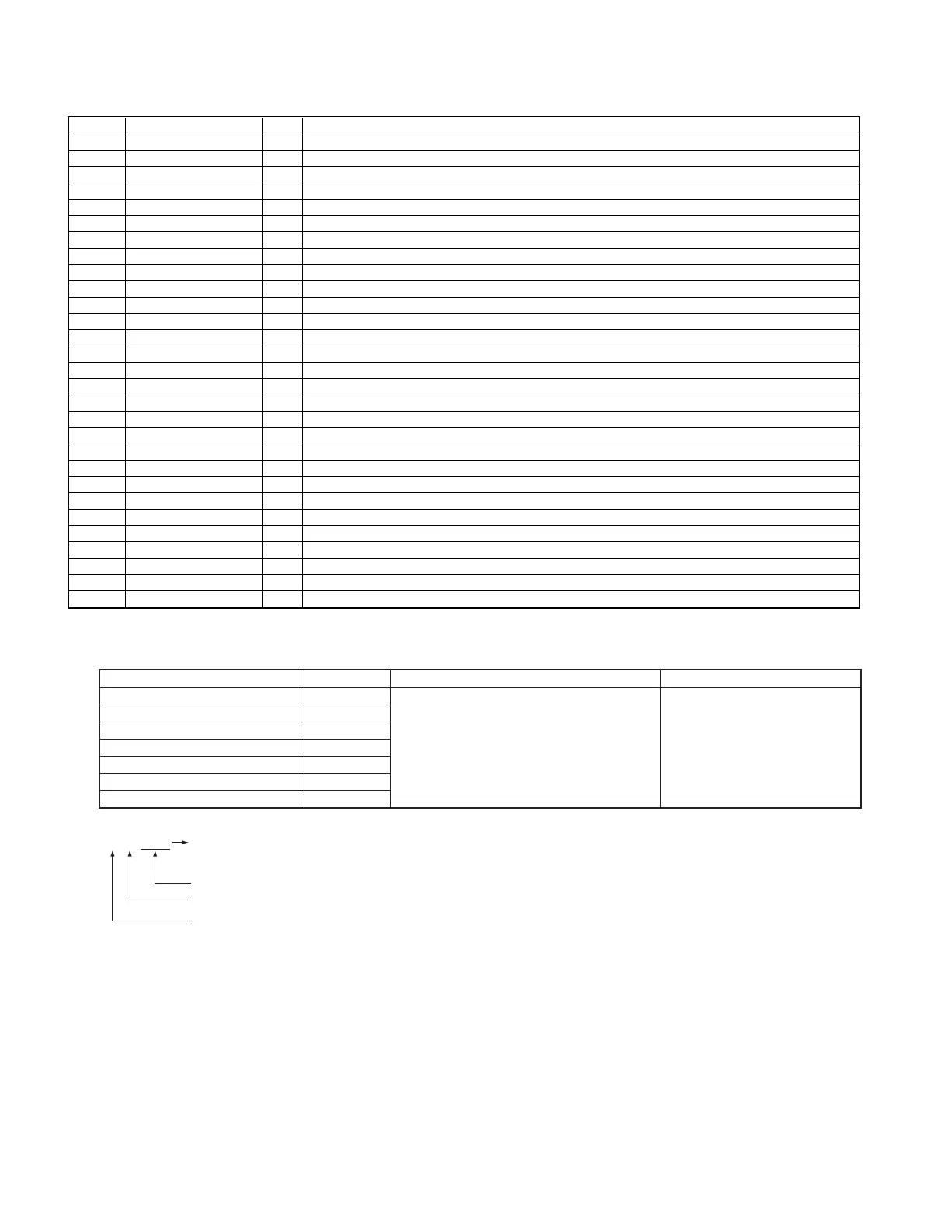
Port # Port Name I/O Description
68,69 NC O No use
70 PCNTO O Power control output port
71 EJECT O No use
72 LDON O Laser diode on signal port(H:ON)
73 A/B I AD/DA converter selector (in or out)
74 SBSY I Synchro signal input port
75 DAPON O No use
76 DFSO O No use
77 DFSI O No use
78 5/3 I GND
79 C/N I GND
80 XRST O MD LSI reset signal port
81 ADMUTE O AD muting port
82 LD+ O Loading motor positive control port
83 LD- O Loading motor negative control port
84 MUTE O Muting signal output port
85 DOUT MT O No use
86-88 TEST(2-0) I No use
89 AVCK3 I Power supply monitor of motor driver
90 AVCK2 I Power supply monitor of AD/DC converters
91 AVCK1 I Power supply monitor of head circuit
92 DTEMP I Temperature monitor port
93 MINF I Disc, rec window,mechanism position
94,95 TEST(K1-K2) I No use
96 GND - GND
97 NC O No use
98 VREF I +3.2V
99 AVCC I +3.2V
100 PR I GND
** In Tape Mode, 4 seconds recording mode only.
*** FTC & Sub clock Oscillation
a) Check the oscillation(yes or no, period)before FTC test mode.
b) Check is 5 times by 200ms. FTC test mode is carried out if one time is OK.
c) Display shows error message as follows and test mode will be stop.
No oscillation î ERR 1 Poor period î ERR 2
7-2 Cancel
a. Cancel the test mode and initialize the unit if pull out the power cord from AC outlet.
b. Cancel the test mode only if the power switch is off.
7-3 Operation in Test Mode
a. Muting does not work except power on/off.
b. No display demo mode.
c. Key is different operation from normal mode.
7. Test Mode
7-1 Setting
Mode Key Setting Remarks
AUX SOUND
TUNER TUNER
CD CD PLAY Insert the AC power cord with pressing
MD -1 MD PLAY the left key
* TAPE TAPE PLAY **TAPE REC key
*** FTC & sub clock oscillation MENU
MD-2 SET
* Operation & Display in Test Mode
E E E E CrO2 detection
L= sw off (-)
Half detection
FWD misrecord detection
RVS misrecord detection
H= sw off (E)

 Loading...