EasyManua.ls Logo

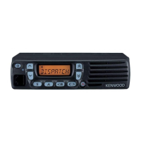
Kenwood TK-7160 Service Manual

Kenwood TK-7160
57 pages
To Next Page IconTo Next Page
Page #1 background imageLoading...
Page #1 background image
© 2005-7 PRINTED IN JAPAN
B51-8722-00
(
N
)
375
VHF FM TRANSCEIVER
TK-7160/7162
SERVICE MANUAL
GENERAL .................................................. 2
SYSTEM SET-UP ...................................... 3
OPERATING FEATURES .......................... 4
REALIGNMENT ......................................... 6
DISASSEMBLY FOR REPAIR ................. 10
CIRCUIT DESCRIPTION .......................... 11
SEMICONDUCTOR DATA ...................... 16
COMPONENTS DESCRIPTION .............. 17
PARTS LIST ............................................. 18
EXPLODED VIEW.................................... 26
PACKING ................................................. 27
ADJUSTMENT ........................................ 28
TERMINAL FUNCTION ........................... 33
PC BOARD
DISPLAY UNIT (X54-3510-10) ............ 34
DISPLAY UNIT (X54-3522-70) ............ 36
TX-RX UNIT (X57-7102-70) ................ 38
SCHEMATIC DIAGRAM.......................... 42
BLOCK DIAGRAM ................................... 48
LEVEL DIAGRAM .................................... 50
SPECIFICATION ................... BACK COVER
CONTENTS
Panel assy
(A62-1107-13)
Key top
(K29-9342-01)
Modular jack
(E08-0877-05)
Panel assy
(A62-1108-03)
Key top
(K29-9342-01)
Modular jack
(E08-0877-05)
TK-7160 E
TK-7162 E
This product uses Lead Free solder.

Other manuals for Kenwood TK-7160

Question and Answer IconNeed help?

Do you have a question about the Kenwood TK-7160 and is the answer not in the manual?

Kenwood TK-7160 Specifications

Power IconPower
operating voltage13.6V DC ± 15%
current drain on standbyLess than 0.4A
current drain on receiveLess than 1.0A
current drain on transmitLess than 8.0A
Operating Environment IconOperating Environment
operating temperature range–30°C to +60°C
frequency stability± 2.5ppm
Receiver Specifications IconReceiver Specifications
sensitivity (12dB SINAD) wide0.28µV
sensitivity (12dB SINAD) narrow0.35µV
selectivity wide75dB
selectivity narrow65dB
intermodulation wide70dB
intermodulation narrow60dB
spurious response75dB
audio power output4.0W
Transmitter Specifications IconTransmitter Specifications
rf power output high25W
rf power output low5W
spurious and harmonics70dB
modulation wide16K0F3E
modulation narrow11K0F3E
fm noise wide45dB
fm noise narrow40dB
audio distortionLess than 3%
Weight and Dimensions IconWeight and Dimensions
width6.30 inch (160 mm)
height1.70 inch (43 mm)
depth5.40 inch (137 mm)
weight2.60 lbs (1.18 kg)

Summary

GENERAL

PERSONAL SAFETY

Safety precautions during operation and servicing.

GENERAL / SYSTEM SET-UP

SERVICE

Guidance on servicing using schematics, PCB views, and alignment procedures.

REALIGNMENT

5. Self Programming Mode

Explains self-programming mode for TK-7160, intended for authorized service personnel.

CIRCUIT DESCRIPTION

Unlock Circuit

Explains the circuit that prevents transmission when the PLL is unlocked.

Power Supply Circuit

Explains the power supply operation, voltage regulation, and protection circuits.

ADJUSTMENT

Test Equipment Required for Alignment

Lists necessary test equipment and their major specifications for alignment.

PCB Section

Details adjustments for Setting, VCO lock voltage, IF coil, and RF bandpass filter.

2. Squelch 9

Procedure for adjusting squelch levels with specific SSG output and modulation.

Receiver Section

Details sensitivity adjustment for wide/narrow channels and SSG output levels.

Transmitter Section

Details adjustments for frequency, maximum power limiting, and high power.

SCHEMATIC DIAGRAM

DISPLAY UNIT (X54-3510-10)

Schematic diagram for the TK-7160 display unit.

LEVEL DIAGRAM

Receiver Section

Level diagram illustrating signal levels in the receiver section.

SPECIFICATIONS

Related product manuals