(No.RA037<Rev.001>)1-7
[Firmware upgrade in Firmware Programing Mode]
(1) Start up the firmware programming software (Updater).
(2) Set the communications speed (normally, 115200 bps)
and communications port in the configuration item.
(3) Press and hold the [Side2] key while turning the trans-
ceiver power ON. Then, the orange LED turns on.
(4) Press "write" button in the window. When the transceiver
starts to receive data, the orange LED turns to green.
(5) If writing ends successfully, the green LED turns to red.
Note:
• This mode cannot be entered if the Firmware Program-
ming mode is set to Disable in the Programming software.
• Normally, write in the high-speed mode.
2.3 CIRCUIT DESCRIPTION
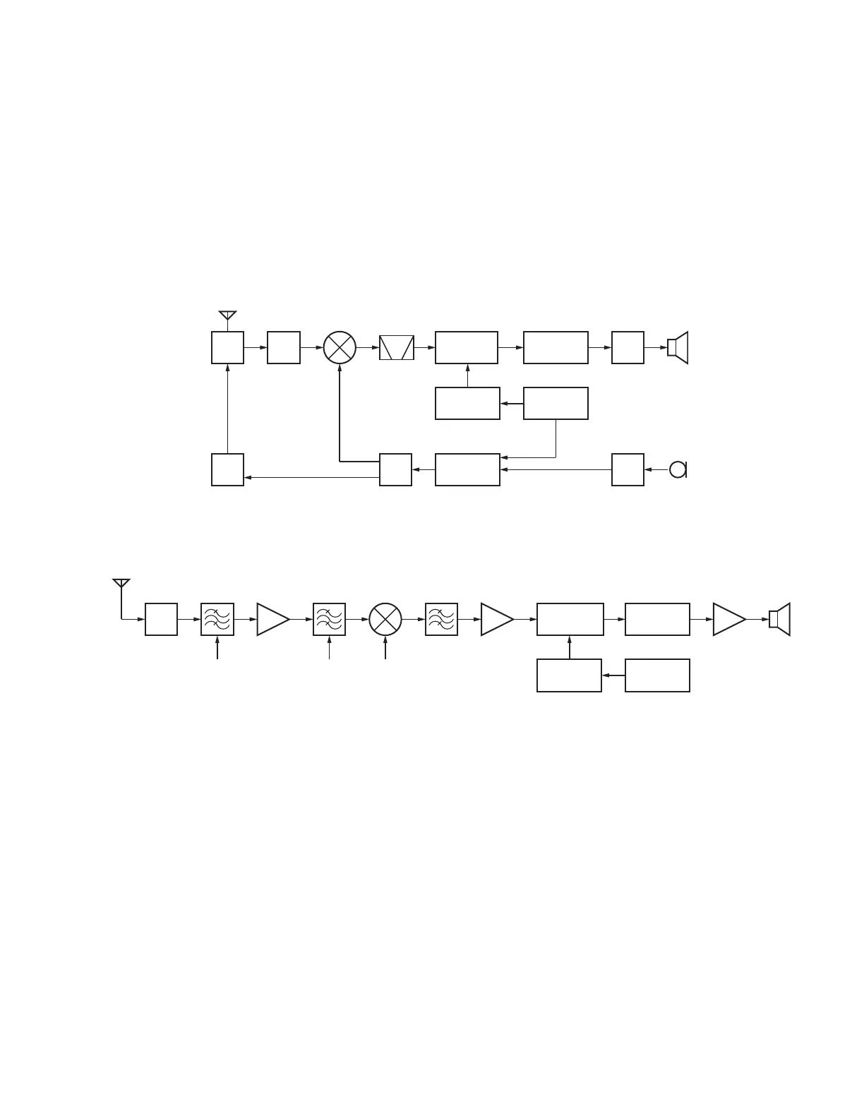
2.3.1 Frequency Configuration
The receiver utilizes double conversion. The first IF is 49.95MHz and the second IF is 450kHz. The first Local oscillator is supplied
from the PLL circuit.
The PLL circuit in the transmitter generates the necessary frequencies. Figure 1 shows the frequencies.
Fig.1 Frequency configuration
2.3.2 Receiver System
The receiver system is shown in Figure 2.
Fig.2 Receiver system
2.3.2.1 Front End (RF Amplifier) Circuit
The signal coming from the antenna passes through the transmit/receive switching diode circuit (D201, D202, D203 and D204) and a
BPF (L415, L416 and L417), and is then amplified by the RF amplifier (Q405).
The resulting signal passes through a BPF (L410,L411 and L413) and goes to the mixer. The BPF is adjusted by variable capacitance
diodes (D400, D401, D402, D403 and D404). The input voltage to the variable capacitance diodes is the regulated voltage output from
the DC amplifier (IC704,IC721).
2.3.2.2 First Mixer
The signal from the front end is mixed with the first local oscillator signal generated in the PLL circuit by Q404 to produce the first IF
frequency of 49.95MHz.
The resulting signal passes through the XF400 MCF to cut the adjacent spurious and provide optimum characteristics, such as adja-
cent frequency selectivity.
2.3.2.3 IF Amplifier Circuit
The first IF signal is passed through a four-pole monolithic crystal filter (XF400) to remove the adjacent channel signal. The filtered
first IF signal is amplified by the first IF amplifier (Q403) and is then applied to the IF system IC (IC400).
The IF system IC provides a second mixer, AGC+BPF, PLL FM detector, noise squelch and RSSI circuit.
The second mixer mixes the first IF signal (49.95MHz) with the signal of the second local oscillator output (Q400) and produces the
second IF signal of 450kHz.
The second IF signal is passed through the internal bandpass filter of the IF system IC to remove the adjacent channel signal. The
filtered second IF signal is amplified by the limiting amplifier and demodulated by the internal discriminator of the IF system IC.
The demodulated signal is routed to the audio circuit.
TX/RX: 400~470MHz
350.05~
420.05MHz
400~470MHz
SPMCF1st MIX
MIC
ANT
ANT
SW
RF
AMP
IF
System
x3
Tripler
PLL
VCO
49.95MHz
50.4MHz
TX
AMP
RF
AMP
AF
AMP
MIC
AMP
Baseband
TCXO 16.8MHz
SP
NT
IC400
IF,MIX,DET
Q404
1st MIX
ANT
SW
Q400
x3 Tripler
2nd Local
X1
TCXO
16.8MHz
Baseband
IC705
BPF1,BPF2(Notch Filter)
BPF
Q405
RF AMP XF400
MCF
Q403
IF AMP
IC709
AF PA
(INT)
BPF1 1st Local
BPF
 Loading...