EasyManua.ls Logo

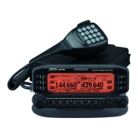
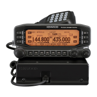
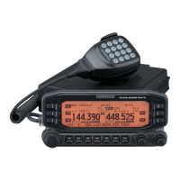
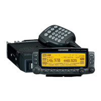
Kenwood TM-D710GA User Manual

Kenwood TM-D710GA
55 pages
To Next Page IconTo Next Page
Page #1 background imageLoading...
Page #1 background image
TM-D710GA/ TM-D710GE
144/440 MHz FM DUAL BANDER/
144/430 MHz FM DUAL BANDER
INSTRUCTION MANUAL
144/440 MHz FM DOUBLE BANDE/
144/430 MHz FM DOUBLE BANDE
MODE D’EMPLOI
DOBLE BANDA DE 144/440 MHz EN FM/
DOBLE BANDA DE 144/430 MHz EN FM
MANUAL DE INSTRUCCIONES
© B62-2562-00 (K, E)
09 08 07 06 05 04 03 02 01 00
Only basic operations are explained in this instruction manual.
For a detailed explanation on the operations, refer to the PDF fi le
supplied on the CD-ROM.
Seules les fonctions de base sont expliquées dans ce mode
d’emploi. Pour le détail sur les autres opérations, reportez-vous
au fi chier PDF à votre disposition sur le CD-ROM.
En este manual de instrucciones solamente se explican las
operaciones básicas. Si desea obtener una descripción detallada
de las operaciones, consulte el archivo PDF correspondiente
incluido en el CD-ROM.
Other manuals for Kenwood TM-D710GA

Questions and Answers:

Kenwood TM-D710GA Specifications

General IconGeneral
Frequency Range TX144-148 MHz, 430-450 MHz
Output Power (VHF)50W
Channels1000
GPSYes
APRSYes
Voltage13.8 V DC
Memory Channels1000
Antenna Impedance50 Ohms
TypeMobile Transceiver
Frequency Range RX118-174 MHz
Modulation ModesFM
DisplayLCD

Summary

NOTIFICATION

Firmware Copyrights

FEATURES

WRITING CONVENTIONS FOLLOWED IN THIS MANUAL

Information on Disposal of Old Electrical and Electronic Equipment and Batteries

NOTICES TO THE USER

FCC WARNING

Warning regarding unauthorized modifications and interference.

DIGITAL DEVICE USER REQUIREMENTS

FCC compliance information for digital device users.

CONDENSATION PRECAUTIONS

How to handle condensation inside the transceiver to prevent malfunction.

SAFETY WARNINGS

Critical safety warnings related to explosive atmospheres, RF burns, and blasting caps.

PRECAUTIONS

IMPORTANT CAUTIONS

General safety precautions to prevent fire, injury, and damage.

PREPARATION

SUPPLIED ACCESSORIES

Lists all items included with the transceiver.

MOBILE INSTALLATION

TX/RX Unit Installation

Instructions for mounting the main transceiver unit inside a vehicle.

Operation Panel Installation

Guide for installing the detachable operation panel in the vehicle.

Power Cable Connection

Details on connecting the transceiver to the vehicle's 12V battery.

FIXED STATION

Operation Panel Installation

Steps for installing the operation panel for fixed station use.

Power Cable Connection

How to connect the transceiver to a separate 13.8V DC power supply.

REPLACING FUSES

OPERATION PANEL AND MICROPHONE CONNECTION

ANTENNA CONNECTION

ACCESSORY CONNECTIONS

External Speakers

How to connect external speakers to the transceiver.

GETTING ACQUAINTED

OPERATION PANEL (FRONT) - In Normal Mode

Overview of the front operation panel controls in Normal mode.

OPERATION PANEL (FRONT) - In Function Mode

Explanation of front operation panel controls when in Function mode.

OPERATION PANEL (REAR & LEFT)

Description of the rear and left side panel connectors and ports.

DISPLAY

Details on the transceiver's display indicators and their meanings.

TX/RX UNIT REAR PANEL

TX/RX UNIT SUB PANEL

MICROPHONE (MC-59)

BASIC OPERATIONS

SWITCHING THE POWER ON/OFF

Instructions for powering the transceiver on and off.

ADJUSTING THE VOLUME

How to control the audio volume using the BAND SEL control.

ADJUSTING THE SQUELCH

Guide to setting the squelch level to eliminate background noise.

SELECTING A BAND

Procedure for selecting between Band A and Band B.

SELECTING DUAL BAND MODE/ SINGLE BAND MODE

SELECTING A FREQUENCY BAND

SELECTING AN OPERATING MODE

VFO Mode

Manual frequency selection using the VFO mode.

Memory Channel Mode

Selecting frequently used frequencies stored in memory.

Call Channel Mode

Quickly accessing preset channels for emergency or immediate calls.

TRANSMITTING

MENU MODE

MENU ACCESS

How to enter and navigate the transceiver's menu system.

MENU CONFIGURATION

CHARACTER ENTRY

Microphone Keypad Character Entry

OPTIONS

MEMORY CONTROL PROGRAM MCP-6A

Details on the software for managing memory channels and settings.

CONNECTING THE PG-5G/ PG-5H INTERFACE CABLES

CONNECTING THE PG-5F EXTENSION CABLE

INSTALLING THE VGS-1 UNIT

MAINTENANCE

GENERAL INFORMATION

Factory alignment and warranty information.

SERVICE

Procedures for returning the product for repair or service.

CLEANING

Instructions for cleaning the transceiver's exterior.

TROUBLESHOOTING

SPECIFICATIONS

Related product manuals