EasyManuals Logo

Kenwood TM-V7A Service Manual

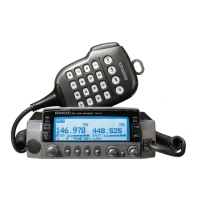
Kenwood TM-V7A
64 pages
To Next Page IconTo Next Page
To Previous Page IconTo Previous Page
Page #56 background imageLoading...
Page #56 background image
TM-V7A/E-TM-V7A/E
WIRING
DIAGRAM
LEVEL
DIAGRAM
5
Transmitter
Section
<
z
iy
MIC
|
|
|
0.09V
-0.5dBm
48dBm
H15dBm
+25dBm
MopytE
ai
J
15A
3
iF
0C13
8V
T
u
!
Vv
1
144MHz
:
50W
.
3
“9
we
l
Q61
430MHz
:
35W
z
| I
*
°
°
o
!
0.05V
-1.5dBm
470Bm
=
-H12dBm
=
+20dBm
=
426dBm
gnu
Le
}
«|
NO
$|
ie
at]
38
!
!
5
3S
©
hited}
e
nw
=
<
|
1
“fh
8
38
3
~
PKD
(data
communications)!
Ole
te
N
Vin
4H
ODT
ot
4
Ss
_
t
a
40mVp-p(1200bps)
|
Icio
|
| |
|
-
S
2Vp-p(9600bps)
:
Q45
Q53 Q57
Q60
x
Oo
&
Note
1:
Set
the
AG
so
that
the
microphone
socket
input
is
3kHz
Note
2:
The
transmit
frequency
is
145.0
or
435.0MHz.
ne
°
x
x
n
deviation
at
1kHz
modulation.
Note
3:
The
Hi/MID/LOW
switch
is
set
to
HI.
noe
eit
©
1
=
@
The
data
communication
connector
input
level
is
3kHz
Note
4:
The
measurements
with
the
power
meter,
except
for
the
otz]/e¥
3
3
@
x
A
215
y
deviation
at
1kHz
modulation
for
1200bps
and
2kHz
ANT
connector,
are
the
values
with
the
APC
off.
~
d
w
a7”
-
F
ww
3
=<
deviation
at
1kHz
modulation
for
9600bps.
~
x
Receiver
Section
-106dBm
-93dBm
-107.5dBm
-103dBm
350mV
C13
~~
“N
-
m
6
z=
>>
>>eozna
>>
6
22
2b
SF
>>
-O
22
1F
2
3}
-
WEDED
EEWARTAASSOOUL
~
eu
DD
MOUWS
Sune
<UEEe
8
24
«12
~
|
—~
| |
<—~
|
or
@
|
TTS
pipuri>
;
-_
wasasnsiw
o
a40
5
“—™~
-110dBm
-103dBm
rs)
~
aJoura>
a
z=
p>
>>>osnnam>
4
o
U>Da>>
>>
=O
2>
&
GOROIGO*®
OD
MWOAD
GISSu-F-=«o.
care
atten,
OO
«a<
WOA>M>>
UK
9
LUD.
0.0.
DE
LUNN
NOOOOUWLE
oO
<WL
tt
DDOOWW
RES
<t
<RLUOC
OE
0
a
BPF
Zz
Zz
7s)
s)
Q13
I
38.85MHz
i
re
|=
45.05MHz
TO
=
<
i
7)
-123dBm -117dBm -110dBm
-107dBm
-106dBm
340mV
>
2
aN
=
8]
o&
oO
ua
ad
52
2
e
oN
S
~
yo
d
x
=m
o
£o°0
Rh
ad
3d
3x
gl
©
Yoo)
g
Oo
A
rs)
az
OSd
OSd
yeaw
7
8
i
O
Kw
we
Go
Sa
Ce
MC.
@
Sd
1Sd
©
ana
z
1
=m
Or
Ne
a
ANT
Q55
a
(ete
~
_
a
nreiil
=
O
moon
.
oO
Oo
*-~~
-103dBm
-103dBm
wo
5
MEME
ES
Oo
-
COUN
<
[exe}
OWwW—
we
oa
=-
P>>rZzwn>
wo
~-
OABBAWOD
ive}
qe
*
“]
vOSND
|.
|
wf
ee
° °
=
\
Ble
°
Q212
|
--
~
in
Pian
L_-,
Note
1:
The
12dB
SiNAD
levels
were
plotted
using
a
standard
Note
2:
The
AF
levels
were
measured
with
an
AF
voltmeter
when
|
p
g
.
|
:
signal
generator
through
a
0.01pF
ceramic
capacitor
at
the
-73dBm
(50pV)
standard
signal
generator
signal
|
E-SA
9 9
|
each
point
from
the
RF
to
the
first
IF.
modulated
by
a
1kHz
modulation
frequency
and
a
3kHz
|
NOI
LdO
a
deviation
was
received
and
the
AF
output
was
adjusted
to
Ve
ee
0.63V/8Q
by
the
AF
VR.
72

Other manuals for Kenwood TM-V7A

Questions and Answers:

Question and Answer IconNeed help?

Do you have a question about the Kenwood TM-V7A and is the answer not in the manual?

Kenwood TM-V7A Specifications

General Specifications IconGeneral Specifications
VHF frequency range144~148MHz
UHF frequency range438~450MHz (U.S.A/Canada)
Antenna impedance50Ω
Usable temperature range-20°C to +60°C (-4°F to +140°F)
Power supply13.8V DC ±15% (11.7~15.8V)
Grounding methodNegative-ground
Frequency stability±3ppm (-10°C to +50°C)
Dimensions (W x H x D)140 x 54.5 x 205.5 mm
Transmitter Specifications IconTransmitter Specifications
High power output50W (VHF) / 35W (UHF)
Mid power outputApprox. 10W
Low power outputApprox. 5W
Spurious emissions-60dB or less
Maximum frequency deviation±5kHz
Audio distortion3% or less (at 60% modulation)
Microphone impedance600Ω
Receiver Specifications IconReceiver Specifications
CircuitryDouble conversion
Intermediate frequency (1st / 2nd)38.85MHz / 450kHz and 45.05MHz / 455kHz
Sensitivity (VHF or UHF band)0.16μV or less (12dB SINAD)
Sensitivity (Sub VHF or UHF band)0.25μV or less
Selectivity (-6dB)12kHz or more
Selectivity (-60dB)28kHz or less
Squelch sensitivity0.1μV or less
Audio output2W or higher (8 ohms, 5% distortion)
Audio output impedance
Weight and Dimensions IconWeight and Dimensions
Weight1.2 kg (2.6 lb)
Dimensions (W x H x D)5.51" x 2.15" x 8.09"

Related product manuals