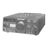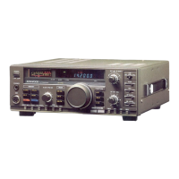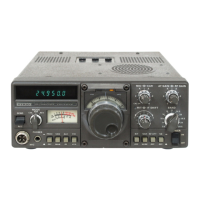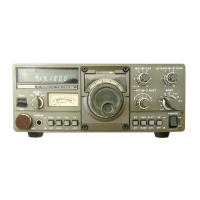
Do you have a question about the Kenwood TS-180S and is the answer not in the manual?
| Brand | Kenwood |
|---|---|
| Model | TS-180S |
| Category | Transceiver |
| Language | English |
Receiver sensitivity, rejection, stability, and selectivity specifications.
Transmitter input power, impedance, suppression, and response specifications.
Four tunable memories for frequency storage and split-frequency operation.
Details on the 200W PEP final stage, reliability, and protection circuits.
Explanation of the single-conversion receiver section with PLL circuit.
Explanation of the transmitter circuit, including power stages.
Operation of the RF speech processor for improved audio output.
Overview of the TS-180's frequency configuration using a PLL circuit.
Description of the PLL ASS'Y unit and its differences from TS-120.
Detailed schematic of the RF unit.
Detailed schematic of the 10W final unit.
Detailed schematic of the VFO unit.
Detailed schematic of the 100W final unit.
Detailed schematic of the counter ASS'Y unit.
Detailed schematic of the PLL ASS'Y unit.
Detailed schematic of the PLL unit.
Detailed schematic of the memory ASS'Y unit.
Parts list for the PLL ASS'Y unit.
Parts list for the PLL unit.
Parts list for the VCO unit.
Step-by-step instructions for installing the memory ASS'Y unit.
Adjustment of the transmitter band-pass filter for optimal performance.
Procedure for adjusting the VCO voltage for frequency stability.
Adjustments for the Phase Locked Loop system, including BPF and mixer balance.
Adjustments related to VCO and scan speed for memory functions.
Procedures for adjusting the ALC meter reading.
Procedures for adjusting the RF meter reading.
Parts list for the VFO ASS'Y unit.
Comprehensive schematic diagram of the entire TS-180 transceiver.