KEOFITT W9 USER MANUAL V.4 PAGE 28
6.7 Flow
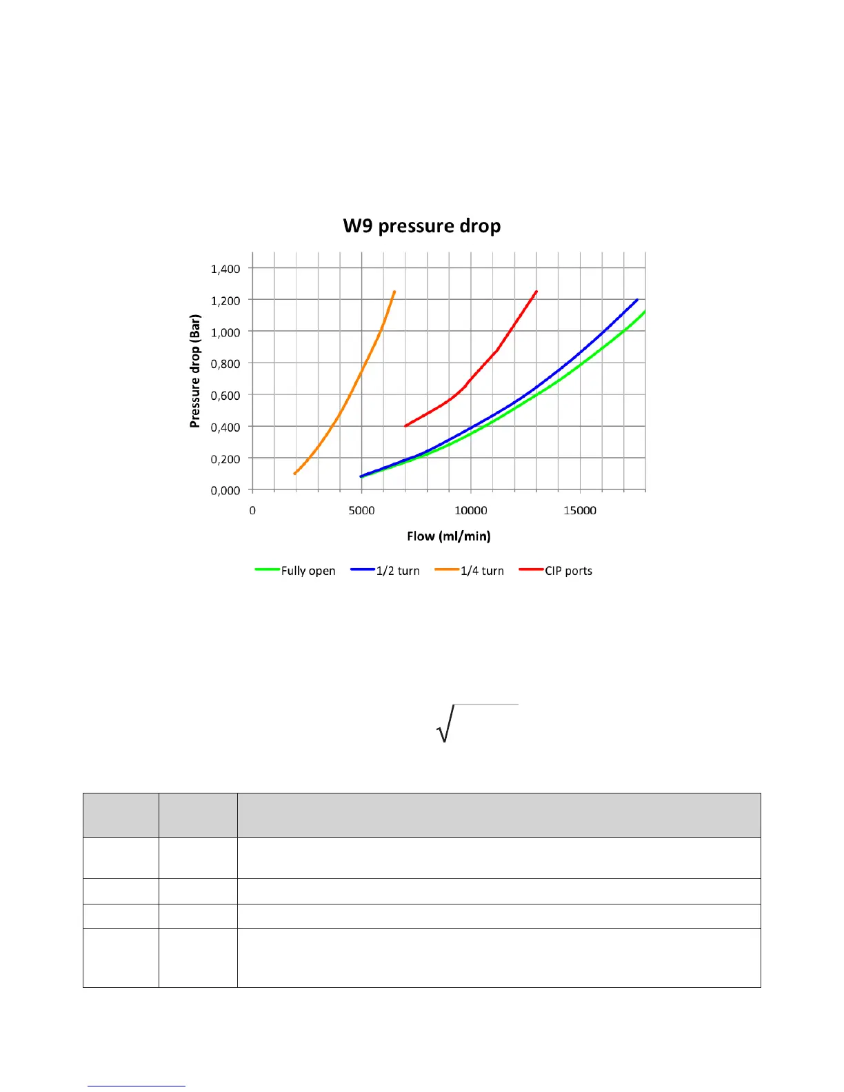
The graphs below illustrate (for water at 20°C/68°F) the following:
• Pressure drop across valve
*
) as a function of the ow for dierent positions of the turn knob
• Pressure drop for ow between the inlet and outlet ports (CIP ports)
*
)From tank/pipe side to lower port (outlet) with upper port blocked.
Based on the tank pressure and the requested sample ow the graphs may be used to get an indication
of to which degree the valve must be opened.
The generally accepted sampling time is around 10 sec. for small samples and around 30 sec. for larger
samples. As usual sample sizes are between 100 ml and 1000 ml the needed ow lies from 600 to 2000
ml/min.
As the pressure on the sample side usually is 0 bar(g) the pressure drop across the valve equals the pro-
cess pressure (tank pressure or line pressure).
The volume ow through a valve is given by:
k
v
= Q
1000x∆p
————
ρ
Symbol Unit Description
m
3
/h Volume ow through the valve
ρ
kg/dm
3
Density of the uid. For Water it is 1.
Δp
bar Pressure drop across valve.
As the gauge pressure at the valve outlet usually is 0 bar(g) the pressure drop is
oen equal to the gauge pressure at the input (the process side)