3-10 Setup Procedure For The Batcher
3-10 Setup Procedure For The Batcher
This section is for models of the batcher with the analog output feature.
card is a (0 - 20) or (4 - 20) mA current sink
. The low (0mA) or (4 mA) and high (20mA) set-
tings may be set at any range. Attempting to set the high setting lower than or the same as
the low setting will display the warning message HIGH
LOW and send the unit back to the
low setting section of the routine. The unit will not exit the ALG OUT routine until a proper set-
ting has been entered. If the displayed rate is below the 4 mA setting, the current driver will
stay at 4 mA. This allows for offsetting the low end of the output signal. If the displayed rate
exceeds the 20 mA setting the current driver will stay at 20 mA.
Note: The current sink follows (tracks) the display.
The Analog Output option is not available on Square Law Analog Input units.
The analog output may correspond to the ratemeter or the totalizer. At this point, the
selection is made by pressing ENT on the appropriate prompt. ANLG RT is the prompt
for the rate meter. ANLG CT is the prompt for the batch totalizer.
Press D to toggle between selections.
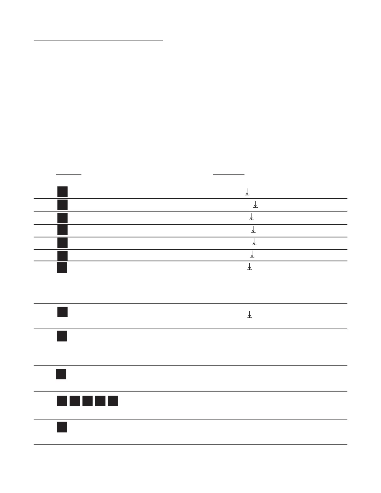
Enters the routine for setting up the Analog Output card.
SET LOW fl ashes then shows the 4 mA Setpoint value.
Clears out existing Low Setpoint value.
Sample Low Setpoint, or enter value from notes or worksheet. (D for decimal point.)
Low Setpoint is stored. SET HIGH fl ashes then shows the 20 mA Setpoint value.