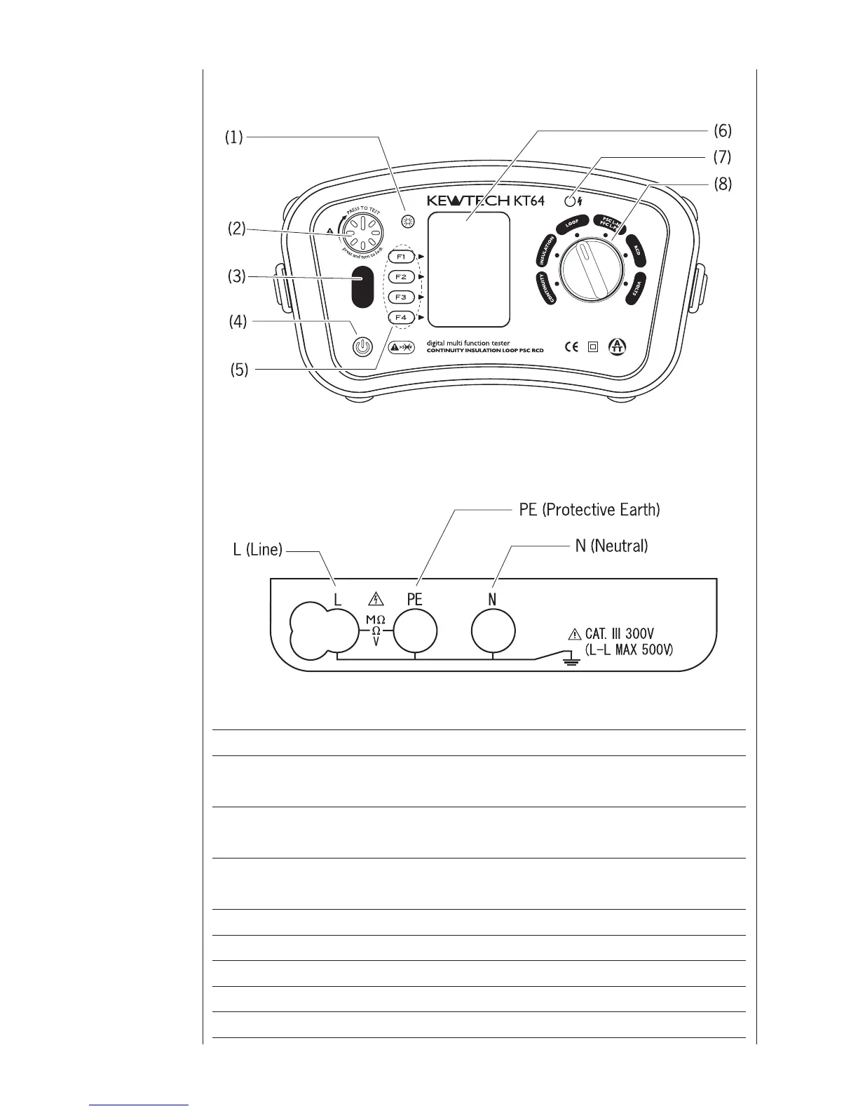
Input Terminal
Name Operation
(1) Back Light Button S wit c h e s o n / of f t h e B ack l i g ht o f t h e
Display(LCD)
(2) Test Button Starts measurements. (press and rotate for
lock down feature)
(3) Touch Pad Checks the electrical potential at the PE
terminal
(4) Power Switch
Power Switch
(5) Function Switch Function setting (F1 ~ F4)
(6) Display (LCD) Dot Matrix LCD 160(W)X240(H)
(7) Insulation resistance LED Alerts that the test voltage is being output
(8) Rotary Switch Selects measurement functions.
2 Instrument
layout
Fig. 1
Fig. 2