17
EN
3 - PRELIMINARY CHECKS
2.4 - List of cables required
The cables required for connection of the various devices in a stan-
dard system are listed in the cables list table.
Before installing the product, perform the following checks and in-
spections:
check that the gate or door is suitable for automation;
the weight and size of the gate or door must be within the operating
limits specied for the automation system in which the product is
installed;
check that the gate or door has rm, effective mechanical safety
stops;
make sure that the product xing zone is not subject to ooding;
high acidity or salinity or nearby heat sources might cause the pro-
duct to malfunction;
in case of extreme weather conditions (e.g. snow, ice, wide tempe-
rature variations or high temperatures), friction may increase, cau-
sing a corresponding rise in the force needed to operate the system;
the starting torque may therefore exceed that required in normal
conditions;
check that when operated by hand the gate or door moves smoothly
without any areas of greater friction or derailment risk;
check that the gate or door is well balanced and will therefore re-
main stationery when released in any position;
check that the electricity supply line to which the product is to be
connected is suitably earthed and protected by an overload and dif-
ferential safety breaker device;
the system power supply line must include a circuit breaker device
with a contact gap allowing complete disconnection in the condi-
tions specied by class III overvoltage;
ensure that all the material used for installation complies with the
relevant regulatory standards.
The cables used must be suitable for the type of installation; for
example, an H03VV-F type cable is recommended for indoor appli-
cations, while H07RN-F is suitable for outdoor applications.
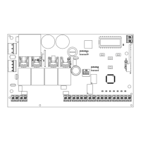
TECHNICAL SPECIFICATIONS:
Power supply (L-N) 230 Vac (+10% - 15%) 50-60 Hz 120 Vac (+10% - 15%) 50-60 Hz
Max motor load 700 W + 700 W 700 W + 700 W
Output for Vdc accessories power and device test power 24 Vdc 500 mA 24 Vdc 500 mA
Output for Vac accessories power 24 Vac 1 A 24 Vac 1 A
Courtesy light output 230 Vac 25 W 120 Vac 25 W
Flashing light output 230 Vac 25 W 120 Vac 25 W
Electric lock output 12 Vac / 15 VA 12 Vac / 15 VA
Maximum work time with settable nominal load Adjustable Adjustable
Pause time Adjustable 0-900 sec. Adjustable 0-900 sec.
Operating temperature -20 °C + 55 °C -20 °C + 55 °C
Power supply line fuses
6,3AF 6,3AF
Accessory fuses DC
500mAF 500mAF
Accessory fuses AC and electric lock
2AF 2AF
* If the power cable is longer than 30 m, a cable with a larger cross-section is required (3x2.5 mm
2
) and safety earthing is necessary in the
vicinity of the automation.
** Two cables of 2 x 0.5 mm
2
can be used as an alternative
ELECTRIC CABLE TECHNICAL SPECIFICATIONS:
Connection cable maximum allowable limit
Power supply line 1 x cable 3 x 1,5 mm
2
20 m *
Motor power supply line 1 x cable 4 x 1,5 mm
2
20 m
Flashing light, courtesy light
Antenna
1 x cable 4 x 0,5 mm
2
**
1 x cable type RG58
20 m
20 m (advised < 5 m)
Electric lock
1 x cable 2 x 1 mm
2
20 m
Transmitter photocells 1 x cable 2 x 0,5 mm
2
20 m
Receiver photocells 1 x cable 4 x 0,5 mm
2
20 m
Sensitive edge 1 x cable 2 x 0,5 mm
2
20 m
Key-switch 1 x cable 4 x 0,5 mm
2
20 m