19
EN
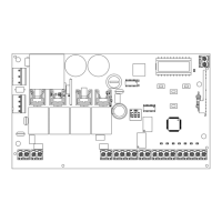
SAFETY AND CONTROL DEVICE CONNECTOR
24 Vac Accessories power 24 Vac, 1 A
EL 12 Vac Electric lock output 12 Vac / 15 VA
+24 Vdc Accessories power positive 24 Vdc, 500 mA
GND Accessories power negative 24 Vdc, 500 mA
+ 24 Vdc
TX PHOTO
Power positive for photocells PH1, PH2; fototest selectable with parameter t.p.h
EDGE Safety edge, ON/OFF NC or 8K2 contact between EDGE and EDGE (caution: when dip switch 1 is set to ON this disables the
EDGE safety input)
PH2 Photocells (opening) NC contact between PH2 and COM (caution: when dip switch 2 is set to ON this disables the PHOTO-
CELL 2 safety input). The photocells trip at any time during automation opening, causing immediate shutdown of the motor;
the automation continues opening on reset of the contact. During closing the photocell trips causing immediate shutdown of
movement; the automation inverts movement to opening when the contact is reset.
PH1 Photocells (closing) NC contact between PH1 and COM (caution: when dip switch 3 is set to ON this disables the PHOTO-
CELL 1 safety input). The photocell trips at any time during automation closing, causing immediate shutdown of movement and
inverting the direction of travel; this photocell is not enabled during opening.
STOP STOP safety device, NC contact between STOP and COM (warning, with dip switch 4 ON the STOP safety device input is off)
This input is classied as a safety device; the contact can be deactivated at any time, cutting out the automation system and
disabling all functions, including Automatic Closure
OPEN OPEN command NO contact between OPEN and COM
Contact for the HOLD-TO-RUN function. The gate OPENS as long as the contact is held down
CLOSE CLOSE command NO contact between CLOSE and COM
Contact for the HOLD-TO-RUN function. The gate CLOSES as long as the contact is held down
PED PEDESTRIAN command NO contact between PED and COM
Used to open the gate partially, depending on the software setting
SS STEPPING command NO contact between SS and COM
Open/Stop/Close/Stop command, or as set in the software
COM Common for the PH1, PH2, STOP, OPEN, CLOSE, PED and SS inputs
SHIELD Antenna - sheath -
SIGNAL Antenna - signal -
4.2 - Display during normal operation
In “NORMAL OPERATING MODE”, i.e. when the system is powered up normally, the 3-gure LCD display shows the following status messages:
MESSAGES MEANING
--
Gate closed or switch-on after shutdown
OP
Gate opening
CL
Gate closing
SO
Gate stopped during opening
SC
Gate stopped during closure
HA
Gate stopped by external event
oP
Gate stopped without automatic reclosure
Pe
Gate in pedestrian opening position without automatic reclosure
-tC
Gate open with timed reclosure
Flashing dash counting in progress
Dash replaced by gures 0..9 countdown (last 10s)
-tP
Gate in pedestrian opening position with timed reclosure
Flashing dash counting in progress
Dash replaced by gures 0..9 countdown (last 10s)
L--
Control unit ready for travel learning cycle
LOP
Learning opening
LCL
Learning closure