3
IL Series-IM_E
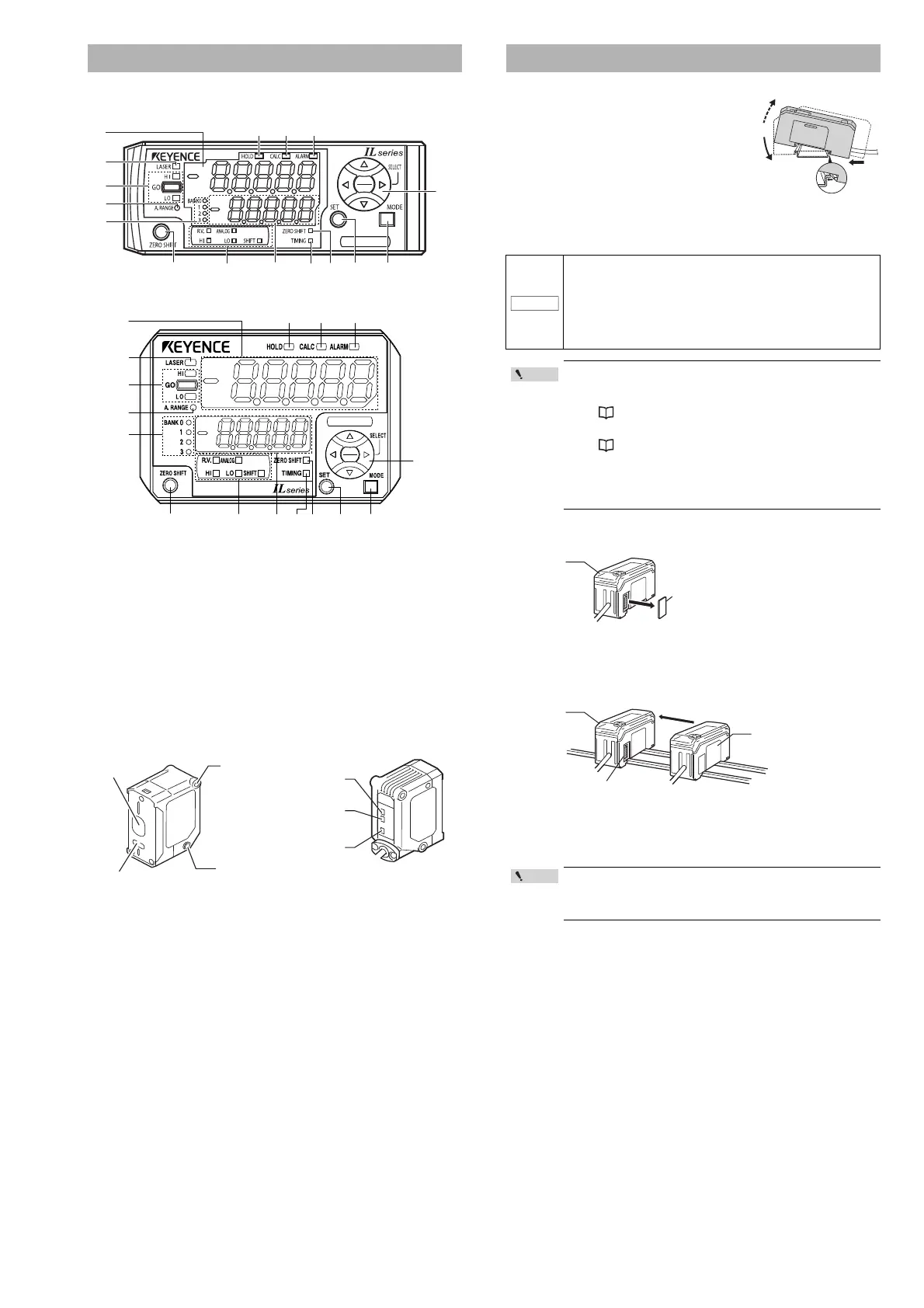
Sensor amplifier unit
DIN rail mount type (IL-1000/IL-1050)
Panel mount type (IL-1500/IL-1550)
(1) Main display
(2) Laser emission warning indicator [LASER]
(3) Judgment indicator [HI / GO / LO]
(4) Analog range indicator [A.RANGE]
(5) Bank indicator [BANK 0 to 3]
(6) Zero shift button [ZERO SHIFT]
(7) Sub display identification indicator [R.V. / ANALOG / HI / LO / SHIFT]
(8) Sub display
(9) Timing input indicator [TIMING]
(10) Zero shift indicator [ZERO SHIFT]
(11) SET button [SET]
(12) MODE button [MODE]
(13) Arrow buttons
(14) Alarm indicator [ALARM]
(15) Calculation indicator [CALC]
(16) Hold indicator [HOLD]
Sensor head
*1 By default (normal display mode), the analog range indicator lights when the
P.V. (judgment value) is within analog output range. The indicator lights within
the following detection range, when the analog output setting is OFF and with
the expansion units.
For more information, such as mode changes, refer to the User's Manual.
*2 By default (normal display mode), the reference distance indicator lights when
the detection distance is within the following range.
For more information, such as mode changes, refer to the User's Manual.
DIN rail mount type, main unit (IL-1000)
Align the claw at the bottom of the main body with
the DIN rail. While pushing the main body in the
direction of the arrow (1), tilt the amplifier in the
direction of the arrow (2).
To remove the amplifier, raise the main body in
the direction of the arrow (3) while pushing it in
the direction of the arrow (1).
DIN rail mount type, expansion unit (IL-1050)
Expansion units must be connected to the main unit before they can be used.
Up to 7 expansion units can be connected to one main unit.
1 Remove the expansion protective cover from the IL-1000 (main
unit).
2 Install the amplifiers (expansion units) onto the DIN rail.
Do the same as instructed under "DIN rail mount type, main unit."
3 Push the expansion unit into the main unit connector until a
clicking sound can be heard.
4 Install the end units (OP-26751: 2 units per set) (sold separately)
on both sides of the amplifiers (main or expansion units). Secure
the end units in place with screws on top (2 on each end unit).
The end units are mounted in the same way as the amplifiers.
Part names
• IL-030: 30 mm ±5 mm • IL-300: 300 mm ±140 mm
• IL-065: 65 mm ±10 mm • IL-600: 600 mm ±400 mm
• IL-100: 100 mm ±20 mm • IL-2000: 2000 mm ±1000 mm
• IL-030: 30 mm ±0.25 mm • IL-300: 300 mm ±7 mm
• IL-065: 65 mm ±0.5 mm • IL-600: 600 mm ±20 mm
• IL-100: 100 mm ±1 mm • IL-2000: 2000 mm ±50 mm
(1)
(2)
(3)
(4)
(5)
(6) (7) (8) (9) (10) (11)
(16) (15) (14)
(13)
(12)
(1)
(2)
(3)
(4)
(5)
(6) (7) (8) (9) (10) (11) (12)
(16) (15) (14)
(13)
IL-030
CENTER
A. RANGE
LASER
Laser
Receiver
Mount
LASER
(
Laser emission
warning indicator
)
A. RANGE
(Analog range indicator)
*1
Mount
CENTER
(Reference distance
indicator)
*2
Laser transmitter
Mounting the Amplifier
• Expansion units must be mounted on the DIN rail.
• When connecting multiple amplifiers (expansion units), first
check to make sure that the power is turned off to all of the
main and expansion units. Installing an expansion unit with
power on may damage this device.
• Push the amplifiers (expansion units) as far as possible into
the main unit. If they are connected at an angle or not inserted
securely, this device could get damaged.
• When connecting the expansion units, make sure to initialize
the expansion units and set the output polarity.
(1) When turning on the amplifier for the first time after
connecting the sensor head please reference
"Operation When the Power is Turned on for the First Time"
(Page 6)
(2) When initializing the unit please reference
"Initial Reset (Initialize)" (Page 8)
• Expansion units with different settings for output polarity
(such as an NPN output expansion unit to a PNP output main
unit) cannot be connected together.
• Expansion units using DIN rail mount cannot be connected to
a panel mount style main unit.
Mount the amplifiers securely using the end units (OP-26751: 2
units per set) (sold separately) or a commercially available DIN
rail mounting tool to prevent the amplifiers from slipping and
coming off from the DIN rail due to machine vibration.
NOTICE
Connecter
Expansion unit
Main unit
Point
 Loading...