4
IL Series-IM_E
Panel mount type, main unit (IL-1500)
1 Make a hole on the panel as shown in the diagrams below.
2 Insert the back side of amplifier to the hole of the panel.
3 Arrange the panel mounting tool in the direction below, mount to
the amplifier from the back and attach the front protection cover
to the amplifier.
To remove the panel mounting tool, widen the
claws at both ends of the panel mounting tool
using a screwdriver, as demonstrated in the
image on the right.
Panel mount type, expansion unit (IL-1550)
Expansion units must be connected to the main unit before they can be used.
Up to 7 expansion units can be connected to one main unit.
1 Make the appropriate number of holes in the panel according to
the number of amplifiers required (expansion units).
For the panel cutting measurement, refer to the "Panel mount type, main unit".
2 Install the amplifiers (expansion units) on the panel.
For the amplifier mounting method, refer to the "Panel mount type, main unit".
3 Connect the amplifiers (main and expansion units) using the
expansion cable (50 mm) supplied with the expansion unit.
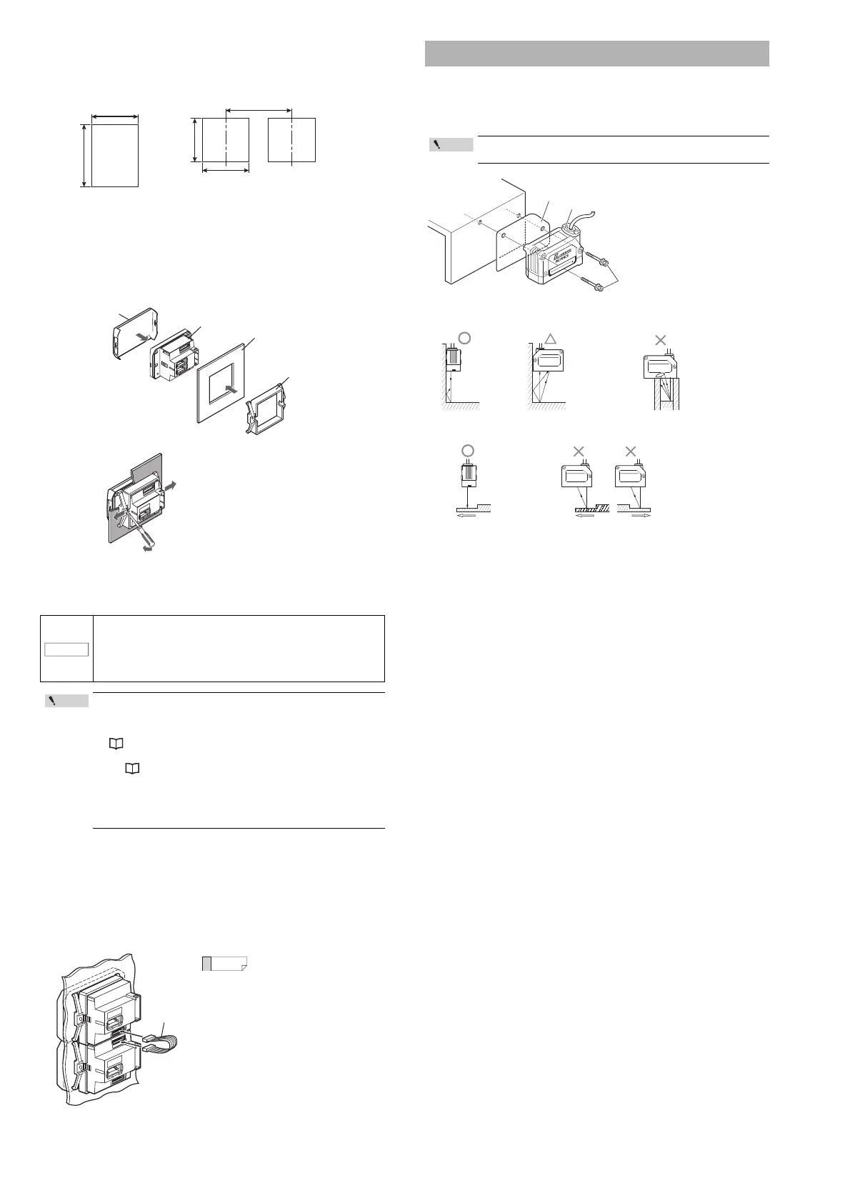
Attach the sensor head using the dedicated mounting bracket.
When the dedicated bracket is not used, place the included insulation sheet between
the mounting surface and the sensor head as indicated in the diagram. (When the
dedicated bracket is used, or when the IL-2000 is used, the insulation sheet is
unnecessary.)
• When connecting the expansion cable, make sure to turn off
the power beforehand. Inserting or removing the cable with
the power turned on may cause damage to the units.
• Push the expansion cable connector securely all the way. If it
is connected at an angle or not inserted securely, the units
could get damaged.
• When connecting the expansion units, make sure to initialize
the connected expansion units and set the output polarity.
(1)
When turning on the amplifier for the first time after
connecting the sensor head please refer to
"Operation When the Power is Turned on for the First Time" (Page 6)
(2)
When initializing the unit please refer to
"Initial Reset (Initialize)" (Page 8)
• Expansion units with different settings for output polarity
(such as an NPN output expansion unit to a PNP output main
unit) cannot be connected together.
• Expansion units using panel mount cannot be connected to a
DIN rail mounted main unit.
When arranging the amplifiers
side by side, the 300 mm
expansion cable (OP-35361) is
required.
· Panel thicknes 1 to 6 mm
· X = 48 × (Number of amplifiers) - 3
+ 0.6
- 0
45 mm
+ 0.6
- 0
45 mm
+ 0.6
- 0
45 mm
X mm
Minimum 85 mm
When stacking
the units vertically.
When stacking
the units horizontally.
Panel mounting bracket
Panel
Amplifier
Front protection cover
Mounting the sensor head
The optical axis may vary by approximately ±1.5 ° (IL-2000), or
±2.0° (IL-030/IL-065/IL-100/IL-300/IL-600).
Insulating sheet
Sensor head
Screws included
with the head
Intelligent-L
AVOID EXPOSURE
LASER RADIATION IS EMITTED
FROM THIS APERTURE
IL
-
030
Tightening torque:
1.2 Nm (12kgf•cm) or less
(IL-030/IL-065/IL-100)
2.7Nm (27kgf•cm) or less
(IL-300/IL-600)
3.0Nm (30kgf•cm) or less
(IL-2000)
Mounting when detecting
targets close to a wall
• The stray
reflections
from the wall
have little
effect.
• Variations in the
detection value
are possible
due to stray
laser light.
Mounting when detecting
targets in a hole
• The target cannot
be detected when
the transmitter or
receiver is blocked.
When detecting uneven workpieces
• Stable detection
possible even on
uneven areas.
• Incorrect
values can be
detected on the
uneven areas.
 Loading...