5
IL Series-IM_E
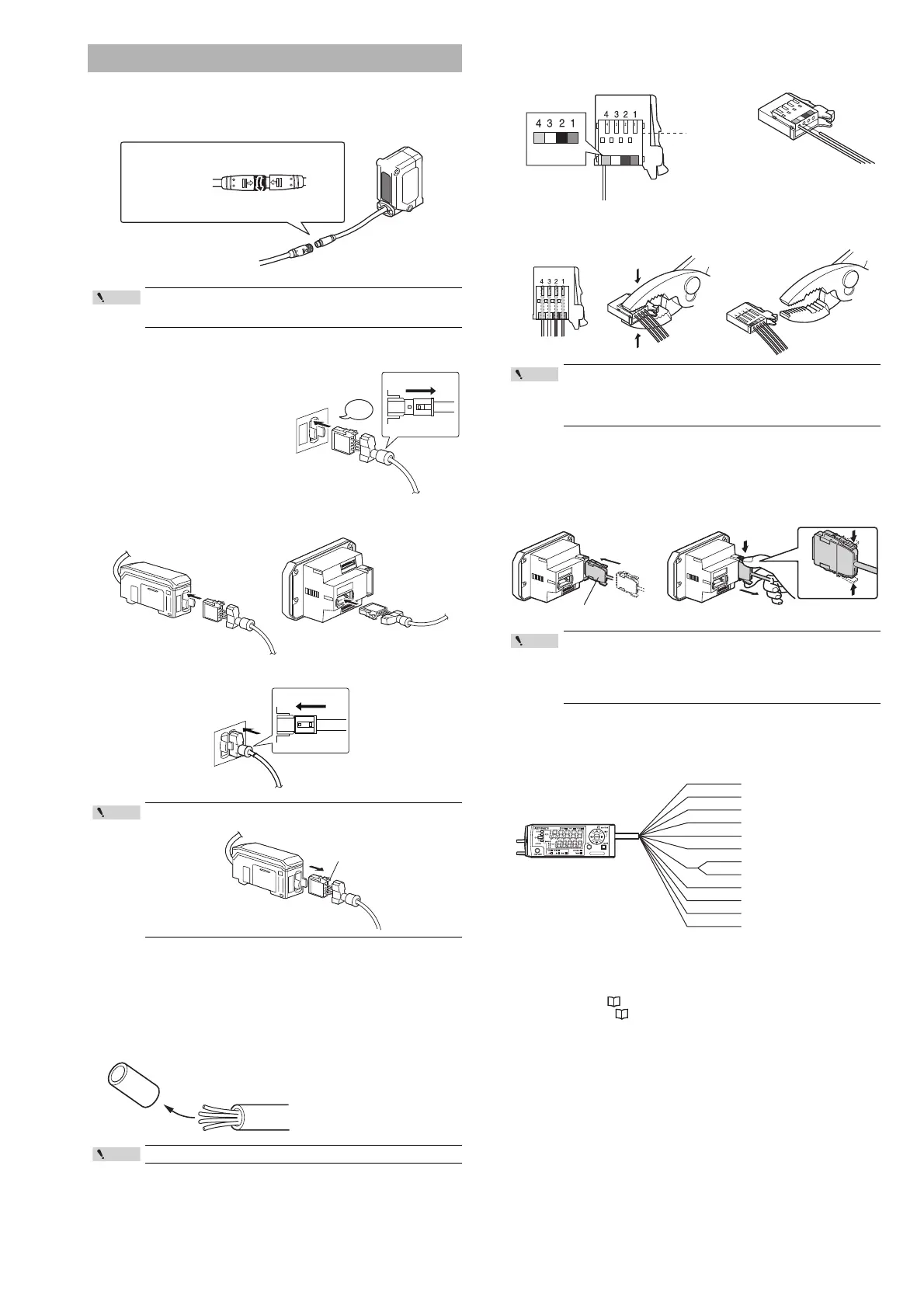
Connecting the sensor head and amplifier
1 Attach the sensor head connection cables to the sensor head
cable.
2 Attach the sensor head connection cable to the amplifier
connector.
Remove the lock cover of the
connector and insert it into the
connectors of amplifier until a
clicking sound can be heard.
3 Attach the lock cover to the connector to secure the cable.
Attaching the sensor head cable connector
(OP-84338: optional)
Cut the sensor head cable to the required length and attach the new connector to
use the sensor.
1 Cut the cable to the required length and strip approx. 15 mm of
insulation from the end.
2 Insert each color coded cable into the same colored marked
points on the connector.
Each cable is secured temporarily when it is inserted completely.
3 Confirm that all the cables are inserted properly into the
connector and crimp them using pliers or a similar tool.
Amplifier wiring
Connecting power/Input-output cable (IL-1500/IL-1550 panel
mount type)
Connect the power/Input-output cable to the panel mount type main unit and
Input-output cable to the expansion units.
Power/Input-output cable
The following information shows the details of power/Input-output cable. For
information about the input-output circuit, see page 11 of this Instruction
Manual.
*1 IL-1050/IL-1550 (expansion unit) do not have brown, blue, or light blue wires.
Power is supplied to the expansion units through the IL-1000/IL-1500 (main
unit).
*2 The Analog output can be set for the following: "Not used (OFF), 0 to 5 V, ±5 V, 1
to 5 V and 4 to 20 mA".
Please reference, "Operation When the Power is Turned on for the First
Time" (Page 6) and "Initial Reset (Initialize)" (Page 8).
*3 In addition to the selections noted on the image above, the external inputs can
also be selected to perform the following: Bank A input, Bank B input, Laser
emission stop input and Not used (OFF).
*4 When connecting six or more expansion units, ensure that the power voltage is
20 to 30 V.
Connection and Wiring
Tighten the connectors securely by hand.
If they are loose, the environment resistance IP67 cannot be
guaranteed.
When removing the sensor head connection cable, push the lock
lever and pull it out.
Do not strip the core wire insulation.
(1) Align the arrow position of the connector to insert.
* For the IL-2000, the direct connector will come out
directly from the sensor head, so there is no arrow.
(2) Rotate the connector screw to tighten.
DIN rail mount type
(IL-1000/IL-1050)
Panel mount type
(IL-1500/IL-1550)
Lock lever
Once the connector has been installed, make sure to connect it
to the amplifier and confirm that the sensor operates normally.
If the sensor head does not function properly, crimp the
connector again using pliers or a similar tool.
Once the connector is crimped, it cannot be reused.
• The number of core wires for the power/Input-output cable for
the main unit is 12, and the number of core wires for the
Input-output cable for the expansion units is 8.
• Power for the expansion units is supplied from the main unit.
• When not using the I/Os of expansion units, cut the cable near
the connector.
Insert further
than here.
Power/Input-output cable
To attach To remove
Point
Brown
Blue
Black
White
Gray
Light blue
Orange
Shield
Pink
Yellow
Pink/Purple
Purple
Green
10 to 30 VDC
0 V
HIGH judgment output
LOW judgment output
GO judgment output
Analog output +
Analog output GND
External input 1
(Zero shift input)
External input 2 (Reset input)
External input 3 (Timing input)
External input 4 (Not Used)
Alarm output
*1 *4
*1
*1
*2
*2
*3
*3
*3
*3
 Loading...