EasyManuals Logo

Keysight Technologies N9010B-526 User Manual

Keysight Technologies N9010B-526
617 pages
To Next Page IconTo Next Page
To Previous Page IconTo Previous Page
Page #202 background imageLoading...
Page #202 background image
202 N9030B PXA Signal Analyzer Service Guide
Front End Control Troubleshooting
A15 Front End Control Description
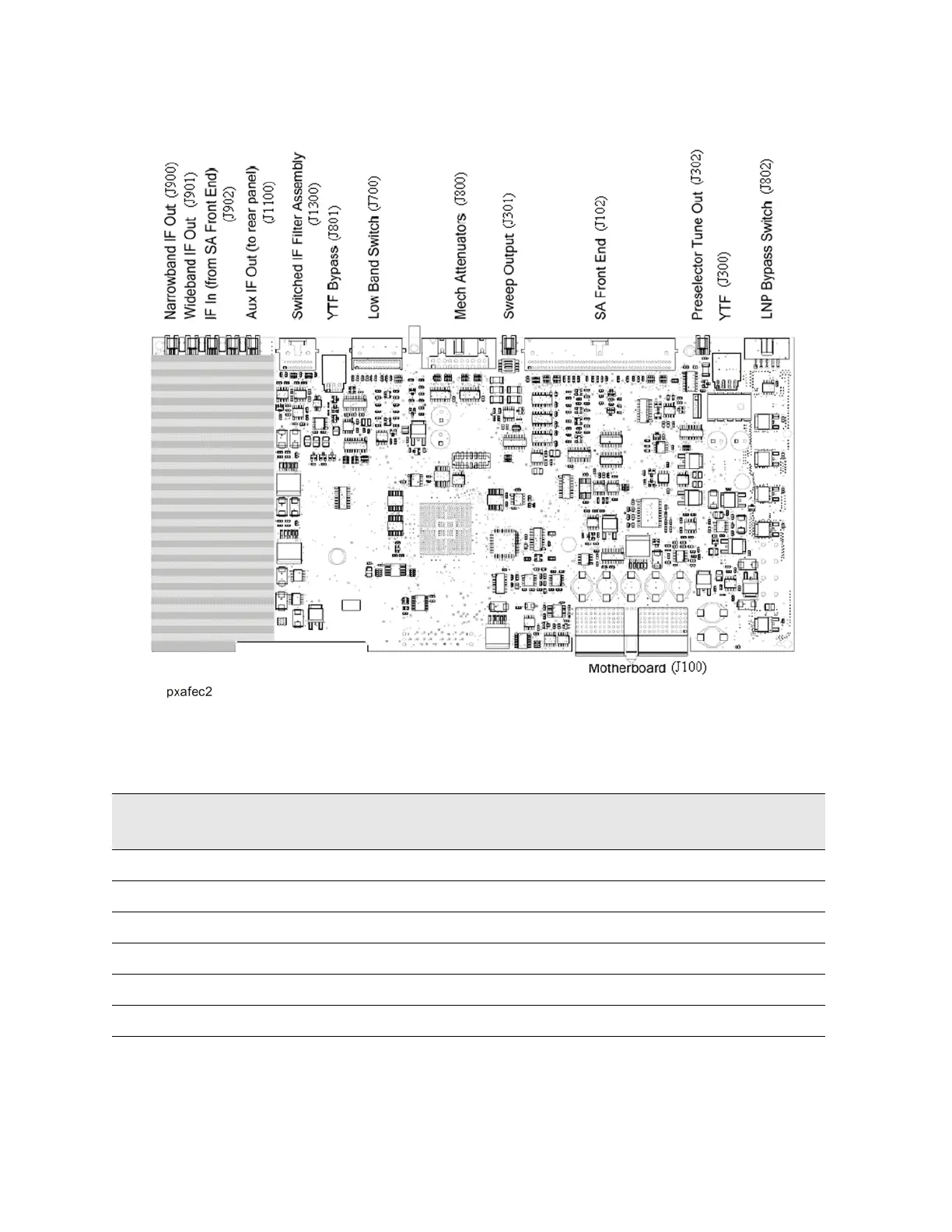
Figure 6-1 A15 Front View, Physical Connectors
The table below describes the connector location and the final destinations of
the RF signal, switch control logic or bias voltage.
Table 6-2 A15 Connectors and Destinations
A15 Connector
Designation
Description Destination
J900 Narrowband I.F. Out To A2
J901 Wideband I.F. Out To A2 or A3 (Wide bandwidths)
J902 322.5 MHz I.F. In From A13 to A15
J903 Ext IF In From A13 to A15 (Option EXM)
J1100 Aux I.F. Out To Rear Panel
J1300 Switched I.F. Filter Out To A13A2

Table of Contents

Other manuals for Keysight Technologies N9010B-526

Questions and Answers:

Question and Answer IconNeed help?

Do you have a question about the Keysight Technologies N9010B-526 and is the answer not in the manual?

Keysight Technologies N9010B-526 Specifications

General IconGeneral
BrandKeysight Technologies
ModelN9010B-526
CategoryMeasuring Instruments
LanguageEnglish

Related product manuals