N9030B PXA Signal Analyzer Service Guide 531
Assembly Replacement Procedures
Motherboard Assembly
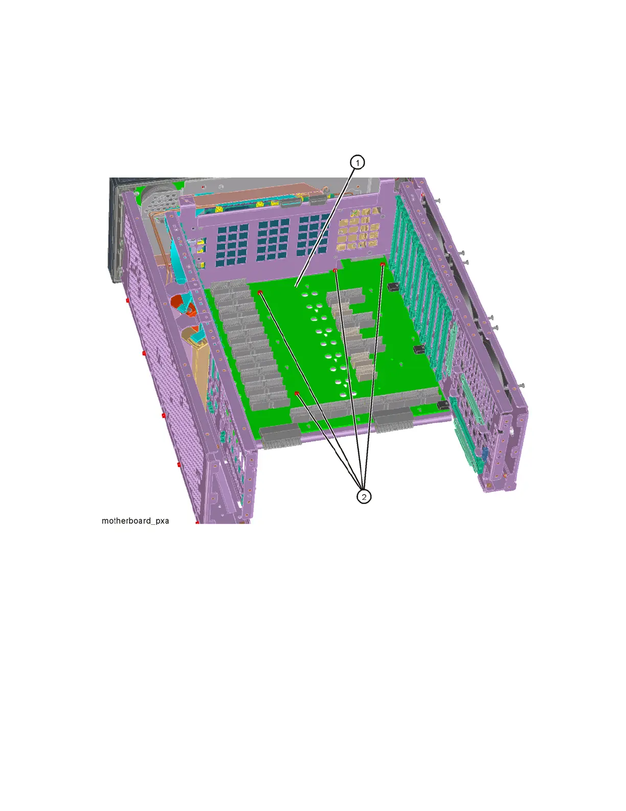
17.Refer to Figure 16-93. Remove the motherboard (1) by removing the four
screws (2) (0515-0372). Slide the motherboard back off the standoffs and
lift it up and out.
Figure 16-93 Motherboard Assembly Removal
Replacement
1. Refer to Figure 16-93. Place the motherboard (1) on standoffs and slide
into position in the chassis and replace the four screws (2) (0515-0372).
Torque to 9 inch-pounds.
2. Refer to Figure 16-92. Replace the left side chassis by replacing the nine
screws (0515-0372). Torque to 9 inch-pounds.
3. Refer to Figure 16-90. Replace the midplane bracket (1) by replacing the
eight screws (2) (0515-0372). Torque to 9 inch-pounds.
4. Replace the fan assembly. Refer to the Fan Assembly replacement
procedure.

 Loading...