540 N9030B PXA Signal Analyzer Service Guide
Assembly Replacement Procedures
Front Frame Assembly
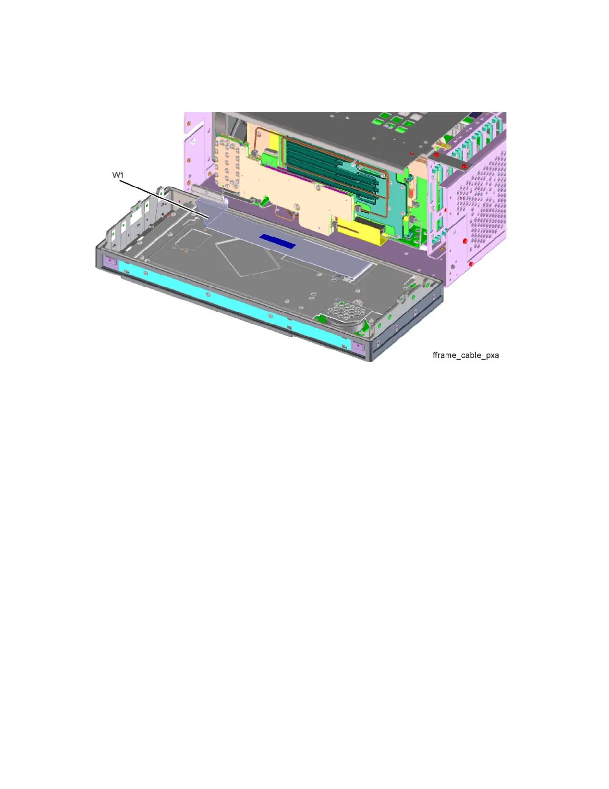
Figure 16-99 Front Panel Cable
Replacement
1. Reattach the ribbon cable W1. Ensure the locking tabs are engaged.
2. Refer to Figure 16-98. Carefully position the Front Frame Assembly onto
the chassis. Ensure no cables are crushed. Replace the eight screws (2)
(0515-2032), four on each side of the chassis. Torque to 9 inch pounds.
3. If option EXM, External Mixing, is installed attach semi-rigid LO/IF cable.
Torque to 10 inch-pounds.
4. Replace the outer case. Refer to the Instrument Outer Case replacement
procedure.

 Loading...