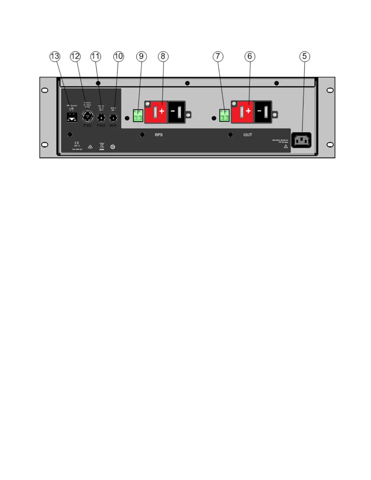
Rear View
1. Line switch Turns the unit on or off.
2. Green Power On light Indicates that the SDS unit has been turned on when illuminated
3. Yellow Connected light Indicates that one or more relays are closed when illuminated
4. Blue Reset light Indicates that the SDS must be reset when illuminated
5. AC input Universal AC input (100-240 VAC)
6. UUT output terminals + and - output connections for powering the UUT
7. UUT sense terminals
1
+ and - connections for local or remote sensing
8. RPS input terminals + and - input connections from the RP7900 unit
9. RPS sense terminals
1
+ and - connections for local or remote sensing
10. DI/DO connector Female connector for digital IO control
11. Fixture Cover connector Male connector for fixture cover (refer to Cover switch)
12. Remote Interface connector Male connector for status and control interface (refer to ESTOP
switch)
13. RPS Control interface Interface connector for the RP7900 series power supplies
Note 1
As shipped, sense terminals are connected for local sensing.
Keysight RP7900 Series Operating and Service Guide 301
Appendix A Keysight SD1000A Safety Disconnect System