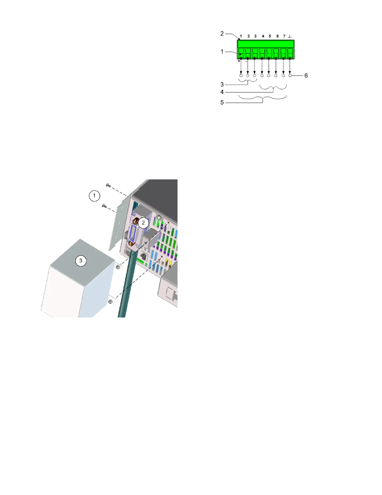
1. Insert wires
2. Tighten screws
3. Fault/Inhibit configurable pins (observe INH
polarity)
4. Output Couple configurable pins
5. Digital IO-configurable pins
6. Signal common
Information on using the digital port is found under Programming the Digital Port. The electrical
characteristics are described in the RP793xA, RP794xA and RP795xA, RP796xA common
characteristics tables.
Interface Cover Installation
The ESD cover and hardware are shipped with the unit (see Items Supplied).
1. Connect the cover flange to the side of the instrument using the two screws provided.
IMPORTANT - This must be done before rack mounting the unit.
2. Connect the LAN, USB, GPIB cable, and digital IO wires (GPIB shown) to the appropriate rear
panel connector.
3. Install the ESD cover to the back of the unit using the two screws. Make sure the cover is inserted
into the flange.
2 Installing the Instrument
86 Keysight RP7900 Series Operating and Service Guide