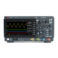
Do you have a question about the Keysight DSOX1202G and is the answer not in the manual?
Connect the power cord and press the power switch to turn on the oscilloscope.
Connect the oscilloscope probe to the BNC connector and the tip to the circuit under test.
Restore the oscilloscope to its default settings for a known operating condition.
Automatically configure the oscilloscope to best display input signals.
Match probe input characteristics to the oscilloscope channel for accurate measurements.
Change the horizontal time/div setting using the sweep speed knob.
Move the trigger point horizontally using the delay (position) knob.
Use horizontal scale and position knobs to pan and zoom acquired waveforms.
View a horizontally expanded version of the normal display in a split-screen.
Change the vertical sensitivity (gain) using the vertical scale knob.
Move the waveform up or down on the display using the vertical position knob.
Add, subtract, or multiply analog channels or perform FFT/low-pass filter.
Adjust the trigger level for a selected analog channel.
Trigger based on a specified edge slope and voltage level.
Trigger on positive or negative pulses of a specified width.
Trigger based on a logical AND combination of channel values.
Trigger based on rising or falling transitions over a specific time.
Trigger on setup and hold violations for clock and data signals.
Enable serial trigger types for protocols like CAN, I2C, LIN, SPI, UART.
Choose how the oscilloscope behaves when trigger conditions are not met.
Start, stop, and capture single acquisitions using front panel keys.
Use horizontal and vertical markers to make custom measurements.
Access the Measurement menu to perform automatic measurements on waveforms.
Create a mask from a golden waveform to verify compliance.
Configure FRA parameters and initiate the frequency sweep.
Choose waveform type (Sine, Square, Ramp, Pulse, DC, Noise) and set parameters.
Save oscilloscope setups, images, and waveform data to internal memory or USB.
Configure oscilloscope remote access via USB device port and LAN interface.
Place the oscilloscope on the network for web interface or remote control.
Run internal self-alignment routine to optimize signal path.
Verify oscilloscope operation through internal hardware tests.
Assign common actions to the Quick Action key for single-press execution.
Connect to the oscilloscope's LAN and access its web server via a browser.
Use the web interface to control the oscilloscope remotely via Browser Web Control.
Configure oscilloscope for CAN signal capture, specifying source, threshold, baud rate.
Set up CAN trigger conditions like SOF, Frame ID, or Error Frames.
Set up oscilloscope to capture and decode CAN signals.
Configure oscilloscope for I2C signal capture, specifying SDA/SCL lines and threshold.
Trigger on I2C conditions like Start/Stop, Missing Ack, or EEPROM Data Read.
Set up oscilloscope to capture and decode I2C signals.
Configure oscilloscope for LIN signal capture, specifying source, threshold, baud rate.
Trigger on LIN Sync Break, Frame ID, or ID and Data.
Set up oscilloscope to capture and decode LIN signals.
Configure oscilloscope for SPI signal capture, specifying clock, MOSI, MISO, CS channels.
Trigger on SPI data patterns at the start of a frame.
Set up oscilloscope to capture and decode SPI signals.
Configure oscilloscope for UART/RS232 capture, specifying bits, parity, baud rate.
Trigger on UART/RS232 conditions like Rx Start/Stop bit or Rx Data.
Set up oscilloscope to capture and decode UART/RS232 signals.
| Bandwidth | 200 MHz |
|---|---|
| Channels | 2 |
| Sample Rate | 2 GSa/s |
| Memory Depth | 1 Mpts |
| Form Factor | Benchtop |
| Record Length | 1 Mpts |
| Waveform Update Rate | 50, 000 wfms/s |
| Vertical Resolution | 8 bits |
| Connectivity | USB, LAN |
| Input Coupling | AC, DC, GND |
| Timebase Range | 5 ns/div to 50 s/div |
| Display | 7-inch WVGA |
| Input Impedance | 1 MΩ |
| Trigger Types | Edge, Pulse, Video |
| Interface | USB, LAN |
| Operating Temperature | 0 °C to 50 °C |
| Input Voltage Range | ±400 V (1 MΩ), 5 V (50 Ω) |
| Maximum Input Voltage | ±400 V (DC + peak AC) |


