Do you have a question about the Keysight DSOX3014T and is the answer not in the manual?
Steps to connect probes to BNC connectors and test points, ensuring proper ground.
Matches probe input capacitance to channel for accurate measurements.
Adjusts the time per division setting using the horizontal scale knob.
Adjusts the horizontal position of the trigger point using the delay knob.
Adjusts the vertical sensitivity (volts/division) using the vertical scale knob.
Moves the waveform up or down on the display using the vertical position knob.
Connects digital probe cable to the DIGITAL connector on the oscilloscope.
Adjusts the vertical level for analog channel edge detection using the Trigger Level knob.
Identifies a trigger by looking for a specified edge (slope) and voltage level on a waveform.
Sets the trigger mode to Auto (default) or Normal for acquiring data.
Uses Run/Stop and Single keys to start, stop, and capture single acquisitions.
Uses horizontal and vertical markers to indicate X/Y axis values for custom measurements.
Uses the Meas key to initiate automatic measurements on waveforms.
Creates a mask based on a reference waveform to verify compliance.
Provides 3-digit voltage measurements on analog channels, asynchronous to acquisition.
Measures frequency, period, or edge events (totalize) on analog channels.
Configures sweep frequencies, channels, and amplitudes for the analysis.
Accesses the Waveform Generator Menu to select and configure output waveforms.
Saves oscilloscope setups, images, or acquired waveform data to internal memory or USB.
Connects the oscilloscope to a network via its rear panel LAN port.
Connects to the oscilloscope's built-in web server using a Java-enabled browser.
Refer to oscilloscope data sheets for complete specifications and characteristics.
Specifies maximum input voltage limits for analog and digital channels.
Connects oscilloscope to CAN signal and specifies source, threshold, baud rate, and sample point.
Sets up triggers for CAN version 2.0A, 2.0B, and CAN FD signals.
Configures oscilloscope to capture and decode CAN/CAN FD signals.
Connects to CXPI signal, specifies source, threshold, baud rate, and tolerance.
Configures oscilloscope to capture and decode CXPI serial signals.
Connects to FlexRay signal, specifies source, threshold, baud rate, and bus type.
Configures oscilloscope to capture and decode FlexRay serial signals.
Connects oscilloscope to serial data (SDA) and clock (SCL) lines, specifies threshold voltage levels.
Triggers on I2C conditions like start/stop, restart, missing ACK, or EEPROM data read.
Configures oscilloscope to capture and decode I2C serial signals.
Connects to clock, MOSI, MISO, and framing signals, specifies threshold, baud rate.
Configures oscilloscope to capture and decode SPI serial signals.
Connects to serial clock, word select, and serial data lines, specifies threshold voltage levels.
Configures oscilloscope to capture and decode I2S serial signals.
Connects to Manchester-encoded bus, specifies signal, bus config, and settings.
| Bandwidth | 100 MHz |
|---|---|
| Channels | 4 |
| Form Factor | Benchtop |
| Vertical Resolution | 8 bits |
| Input Coupling | AC, DC, GND |
| Timebase Range | 5 ns/div to 50 s/div |
| Waveform Update Rate | Up to 1, 000, 000 waveforms per second |
| Input Impedance | 1 MΩ |
| Connectivity | USB, LAN |
| Maximum Input Voltage | 300 Vrms |
| Trigger Types | Edge, Pulse Width, Video, Pattern, Sequence |
| Operating Temperature | 0 to +50 °C |
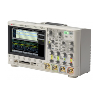
| Display | 8.5-inch WVGA (800 x 480) capacitive touchscreen |


