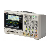
Do you have a question about the Keysight DSOX3024T and is the answer not in the manual?
Step-by-step instructions to power on the oscilloscope and its power requirements.
Lists available hardware-accelerated serial decode options and their licenses.
Sets the vertical level for analog channel edge detection using the Trigger Level knob.
Identifies triggers based on a specified edge slope and voltage level.
Chooses how the oscilloscope acquires and displays waveform data.
Accesses the Measurement Menu to add and configure automatic measurements.
Explains measurements related to voltage, such as Peak-Peak, Maximum, and Amplitude.
Automatically creates a mask based on a known good waveform.
Configures and initiates the frequency response analysis sweep.
Allows creation and modification of custom arbitrary waveforms.
Establishes the oscilloscope's network connection for remote control and printing.
Provides access to remote front panel views and SCPI command window.
Connects and configures the oscilloscope for capturing CAN signals.
Sets up triggers for CAN version 2.0A, 2.0B, and CAN FD signals.
Configures the oscilloscope for decoding CAN and CAN FD serial bus signals.
Configures the oscilloscope for decoding CXPI serial bus signals.
Configures the oscilloscope for decoding FlexRay serial bus signals.
Connects and configures the oscilloscope for capturing I2C signals.
Sets up triggers for I2C start/stop conditions, restarts, and data values.
Configures the oscilloscope for decoding I2C serial bus signals.
Configures the oscilloscope for decoding I2S serial bus data.
Configures the oscilloscope for decoding Manchester serial bus data.
Configures the oscilloscope for decoding MIL-STD-1553 serial bus data.
Configures the oscilloscope for decoding SENT serial bus data.
Connects and configures the oscilloscope for capturing UART/RS232 signals.
Sets up triggers for UART/RS232 Rx start/stop bits, or data values.
Configures the oscilloscope for decoding UART/RS232 serial bus data.
| Brand | Keysight |
|---|---|
| Model | DSOX3024T |
| Category | Test Equipment |
| Language | English |


