3-4 Electronic Calibration Modules Reference Guide
Operating ECal Module
Setting Up a Calibration
3-
9. Perform a 1-port calibration by clicking the softkey of the selected port.
10.Refer to the ENA User’s Guide or Online Help for more details on
performing various types of 1-port calibrations. Refer to your instrument’s
Online Help/User’s Guide on http://ww.keysight.com.
11.When the calibration is complete, remove the ECal module, and connect
the DUT.
Required Procedure for All Calibrations (FieldFox)
For all calibration types, complete the following steps:
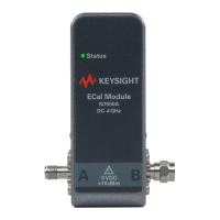
1. Connect an ECal module to the FieldFox having the appropriate frequency
range and connector type.
2. Wait until LED turns green.
3. Set up the analyzer in the measurement configuration. Select the
frequency, power, sweep and other stimulus settings.
4. View the response (uncorrected) and optimize the analyzer settings as
needed.
5. Connect the ECal module to the measurement ports.
6. Set instrument to frequency range that is compatible with your ECal
module.
7. Navigate to Cal 5 > Mechanical Cal / ECal.
For each test port to be calibrated, press the Change DUT Connectors and
follow the prompts.
Excessive torque can damage ECal module connectors. See Table 4-1 on
page 4-21 for the required torque setting for each connector type.
For optimal results, terminate any unused ECal ports with a 50 ohm load.
Verify the FieldFox is set to a frequency range that is within the ECal
module’s range. If the frequency start and or stop frequency are outside
the range of the ECal module, the FieldFox does not recognize the ECal
module.
IMPORTANT: Until the correct connector-type is selected for your ECal
module, the ECal module choice(s) will not be visible in the Select
CalKit table.