1-12 Keysight Technologies Startup Guide
Getting Started
STEP 4. Install the P937xA Network Analyzers
1-
Installation Procedure
This procedure assumes you have Option Y1701A latch keys and jumpers kit.
Learn more, refer to, “Hardware Requirements” on page 8.
1. If using only one P937xA module, leave the 50 ohm loads attached as
shown in Figure 1-3 on page 12.
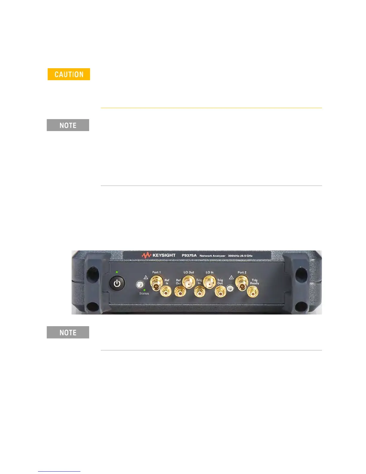
Figure 1-3 Single P937xA Network Analyzer Module Configuration
2. As seen in Figure 1-4 on page 13, each module is shipped with two
50 ohm loads attached to each module. To enable connections between
P937xAs, some of these loads must be removed. To remove the loads, use
the socket adapter, seen in Figure 1-5 on page 13, attached to the 8 lbf-in
(0.91 N.m) torque driver.
a. On the first P937xA, remove the 50 ohm load from the LO Out port.
Leave the load installed on the LO In port.
Position the P937xA to provide ample space between the chassis fan
intake and exhaust vents. Blockage by walls or obstructions affects the air
flow needed for cooling. (Refer to Figure 1-2 on page 11 and to the P937xA
chassis “Space Requirements” on page 12 for more information about
cooling.)
IMPORTANT!
If you are using a multiport (stacked) configuration ensure you have the
correct master P937xA assigned. Refer to,
https://www.keysight.com/find/usb-vna (i.e., click on your USB-VNA
model > Resource Center > Manuals > USB VNA Help File and search for
the "Multiport and Multisite Configuration" topic (you will need to save the
file to your desktop to view the files)). See also, USB Chassis Soft Front
Panel Help File.
In the following instructions, two P937xA network analyzer modules are
configured. Use these instructions as a general guide if installing a
different number of modules.
 Loading...


