Keysight Technologies Startup Guide 1-15
Getting Started
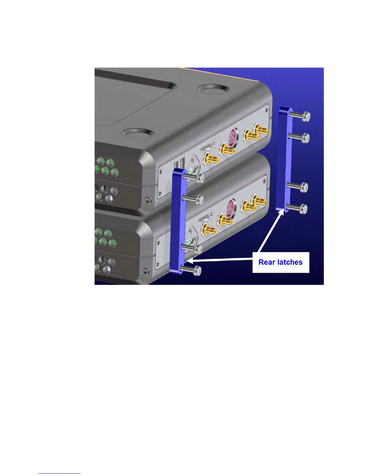
STEP 4. Install the P937xA Network Analyzers
Figure 1-7 Assemble rear latches and screws (0515-0664 screws (x8) and P9375-20018
rear latches (x2)
6. Install a semi-rigid cable (P9375-20014), seen in Figure 1-8, between the
Trig Out port and the Trig In port on each of the P937xA pairs (1 & 2).
7. Install a semi-rigid cable (P9375-20015), seen in Figure 1-8, between the
Ref In port and the Ref Out port on each of the P937xA pairs (1 & 2).
8. Tighten the semi-rigid cables using the socket adapter, seen in Figure 1-5
on page 13, attached to an 8 lbf-in (0.91 N.m) torque driver.
9. Install a semi-rigid cable (P9375-20013), seen in Figure 1-8, between the
LO In port and the LO Out port on each of the P937xA pairs (1 & 2).
 Loading...


