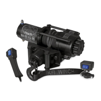
6
SE35
Mounting bolts must be SAE grade 5 or better
and torque to 17 ft. lbs.
Before you start to install this winch,
disconnect the vehicle ground and positive
leads from the battery.
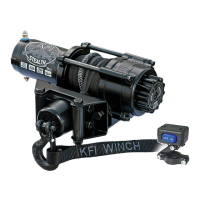
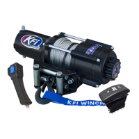
This KFI 3,500 lb winch is designed with a bolt
pattern that is standard in this class of winch.
Many winch mounting kits are available that
utilize this bolt pattern for the most popular
ATV’s and UTV’s. You can nd most of the
ATV/UTV winch mounts on our Website
www.kproducts.com
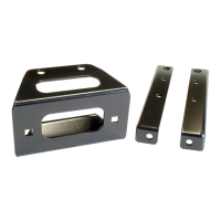
1. Install the winch and fairlead with the
supplied hardware per the instructions
provided with the model specic mounting
kit or prepare a at, secure mounting
location for the winch.
Step 2-Mount the Contactor
1. Find a location for the contactor. If the
Model specic mounting kit does not indicate
a recommended contactor location, then
it is recommended that the contactor be
mounted close to the battery in a clean dry
location. Make sure the location you chose
allows sufcient clearance from all metal
components. Drill mounting holes if required.
Once location is found do not install until all
wiring is completed.
Step 1-Mount the Winch
Installation
CAUTION
WARNING
2. Attach the winch using the M8 x 25 or 30
bolts and washers through the fairlead
bracket or model specic mount and then
into the winch.
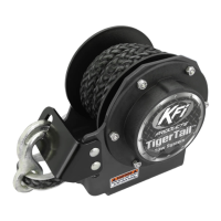
3. Disengage the clutch by rotating the clutch
cap to the “FREESPOOL” position. Release
the synthetic rope and pull through the roller
fairlead.
4. Attach the clevis hook and hand strap to the
cable.
NOTE
If you chose not to use a model specic
mounting kit, you will need to drill holes in the
structural support of the vehicle. Be certain
that your structural support will stand up to the
pulling forces of this winch.
Installation
1"
3/16"
13/16"
Not to scale. Do NOT use as a template
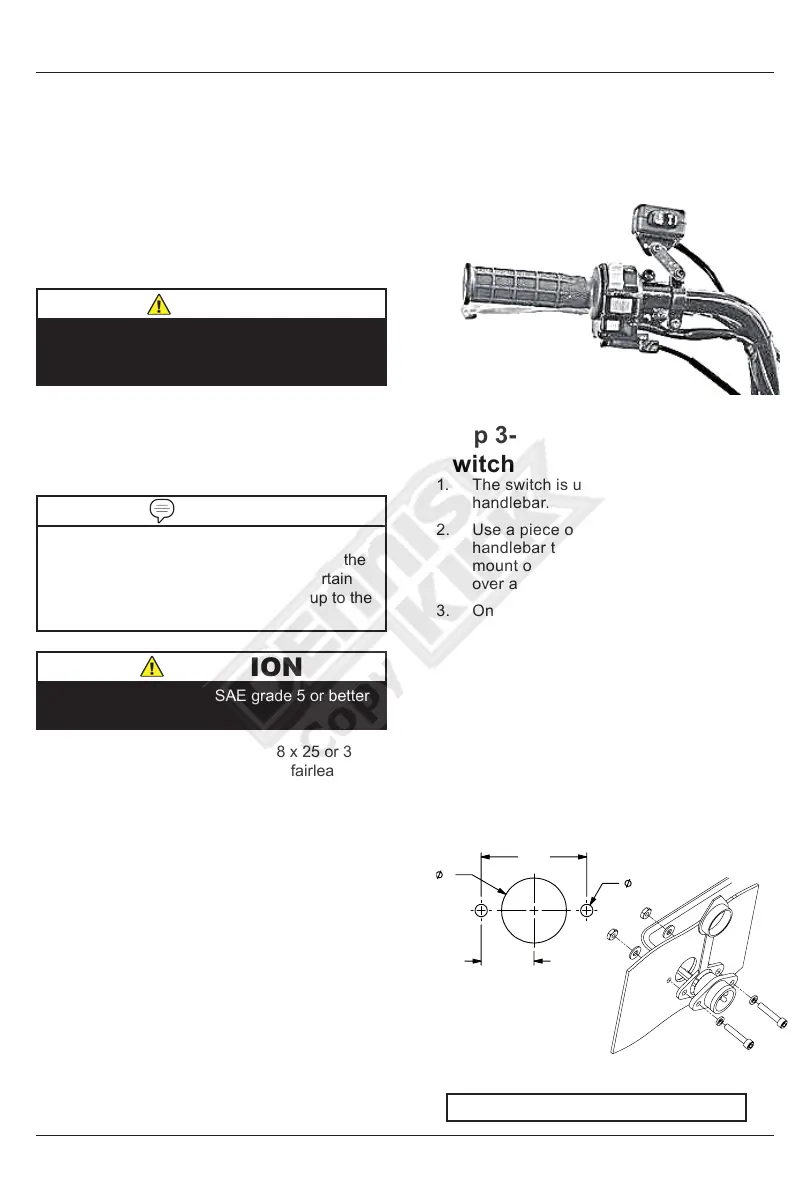
Step 3-Mount the Handlebar
Switch
1. The switch is usually installed on the left
handlebar.
2. Use a piece of electrical tape around the
handlebar to help prevent rotation of the
mount on the handlebar. Do NOT tighten
over any hoses or cables.
3. Once your switch is mounted you can
route the wires back to where your
contactor is located.
4. Splice the end of the red wire to an ignition
(keyed) controlled power source using the
supplied wire splice. You may need to use
a test light to locate a suitable wire. The
wire should only have power when the key
is in the ON position.
5. Make sure the handlebars have full range
of motion and then secure the switch’s
cable with the supplied cable ties.