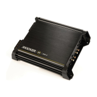
FourChannelModels:
OX.4SeriesAmplifier
Owner'sManual
OX200.4
Congratulations on
your
KICKER purchase!
Please record your purchase
information and keep your sales
receipt for validation of warranty.
Installation
Authorized Kicker Dealer:
Purchase Date:
Amplifier Model Number:
Amplifier Serial Number:
1.
Mounting Choose a structurally sound location to mount your Kicker amplifier. The controls on the
top
of the amplifier need to be accessible for adjustment. Make sure there are no items behind the area
where the screws will be driven. Choose a location that allows at least 4" (10cm) of open ventilation for
the amplifier.
If
possible, mount the amplifier
in
the climate-controlled passenger compartment.
Drill
four
holes using a 7/64" (3mm) bit and use the supplied #8 screws to mount the amplifier.
2.
Wiring Disconnect the vehicle s battery to avoid
an
electrical short. Then, connect the ground wire
to
the amplifier. Make the ground wire short, 24" (60cm) or less, and connect it to a paint and corrosion free
solid metal area of the vehicle's chassis. Adding
an
additional ground wire
of
this same gauge (or larger)
between the battery's negative post and the vehicle chassis
is
recommended.
The
OX
amplifier has dual input sensitivity differential RCA inputs which will receive either high or low
level signals from your car stereo's source unit. Ideally, when connecting the source unit
to
the amplifier
the
OX
amplifier's input
level
switch should be set to "LO" and a low-level signal should run from the
source unit's stereo RCA output to the stereo RCA input
on
the end panel of the amplifier using RCA
interconnect cable.
If
a low-level stereo RCA output
is
not available on the source unit, the signal can
be delivered to the amplifier using the high-level speaker outputs on the source unit. Set the input
level
switch on the end panel of the amplifier to "HI". Crimp and solder RCA connectors
to
the end of the
speaker wire running from the high-level speaker outputs on the source unit and connect the wire to the
RCA Inputs on the end panel of the amplifier as shown
in
Figure
1.
Keep the audio signal cable away
from factory wiring harnesses and
n Figure 1
h .
'If
d High-level Speaker
Output
Wire
i!UIJ
0 Core Cable
ot er power wIring. you nee to
~ToSourceUnit
~
Q
~,
/-"..-------.-....
cross this wiring, cross it at a 90
,---_~....,..-----~
?
~.
~?----.11111""'"
degree angle. 0 oGround
or
Shielding
Install a fuse within 18" (45cm) of the battery and in-line with the power cable connected
to
your
amplifier.
If
you ever need to remove the amplifier from the vehicle after
it
has been installed, the ground
...
wire should be the last wire disconnected from the amplifier--just the opposite as when you installed
it.
See the chart below for power and ground wire size, and fusing recommendations.
Mode1DX200.4 1
(ONE)
30
AMPERE FUSE PowerGroundWire 8GA
3.
Configuration The following diagrams show the most common configurations for your Kicker
OX
series amplifier.
TwoChannelOperation (Stereo)
DXA
series amplifiers are capable of operating into a minimum
impedance of 2 ohms per channel
in
stereo operation. See Figure
2.
BridgedOperation (Mono)
DXA
amplifiers are capable of operating into a minimum impedance of 4
ohms when
in
bridged operation. See Figure
3.
StereoBridgedOperation (Simultaneously) The
DXA
series amplifiers are capable of operating into a
minimum impedance of 4 ohms bridged and 2 ohms per channel
in
stereo operation. See Figure
4.
2
DX.4AMPLIFIER