16
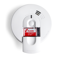
• A maximum of 24 Kidde Safety devices may be interconnected in a multiple station arrangement.
The interconnect system should not exceed the NFPA interconnect limit of 12 smoke alarms and/or
18 alarms total (smoke, CO, Smoke/ CO Combination, heat, etc.). With 18 alarms interconnected, it is
still possible to interconnect up to a total of 6 remote signaling devices and/or relay modules.
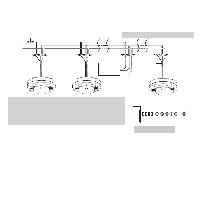
• Figure 9-D illustrates interconnection wiring. Improper connection will result in damage to the alarm,
failure to operate, or a shock hazard.
• Make certain alarms are wired to a continuous (non-switched) power line.
NOTE: Use standard UL Listed household wire (as required by local codes) available at all electrical
supply stores and most hardware stores.
NOTE: AC power should be turned off at this stage.
• For best results to minimize nuisance alarms, interconnected alarms should be on a dedicated line.
If not on a dedicated line, it is suggested that the smoke alarms share a lighting load circuit that
does not have a dimmer associated with it. If receptacles must be placed on the same line it is
suggested that they be placed ahead of the smoke alarms (see Figure 9-E). This will prevent large
voltage drops from occurring between the first and last alarm in the circuit.
Figure 9-E
Kidde Relay Module
SM120X, CO120X
or both
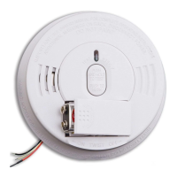
Wires on alarm harness: Connected to:
Black: Hot side of AC line
White: Neutral side of AC line
Red: Interconnect lines (red wires) of other
units in the multiple station set-up
Panel
Receptacles Interconnected alarms
Wiring practice that has had good results
in preventing nuisance alarms
L
N
FUSE OR CIRCUIT BREAKER
Additional
Alarm
RED
BLACK
WHITE
Additional
Alarm
RED
BLACK
WHITE
RED
BLACK
WHITE
Optional
Accessory
First
Alarm
Figure 9-D, Interconnect Wiring Diagram