13
8. Installation And Activation
NOTE: One of the following steps must be taken to ensure activation:
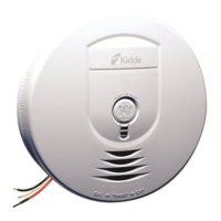
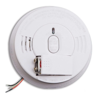
A. Locate the red wheel on the back of the unit - turn the red wheel to
the “ON” position using the included white activation tool or a
standard screwdriver. Battery will remain active to allow for
installation on mounting bracket.
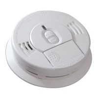
B. Orient the unit with LED pointing to the right as shown in Figure 8-B,
and rotate the unit a full 90 degrees clockwise onto the mounting
bracket. To allow for installation, battery will remain active when unit
is removed from mounting bracket.
NOTE: The battery activation is a one-time feature that occurs when
the alarm is rotated fully onto the mounting bracket. Upon initial
power being applied, a voice “Push Test Button” will be heard. After
activation, the battery cannot be turned off, and can only be
discharged at the end of product life. If the alarm is removed from
the mounting bracket, the battery will remain active.
See Permanently Disable Alarm / Discharge Battery section.
After selecting the proper location for your alarm, attach the mounting
bracket to the wall or ceiling. To ensure aesthetic alignment of the alarm
with the hallway, or wall, the “A” line on the mounting bracket should be
parallel with the hallway when ceiling mounted, or horizontal when wall mounted.
• Install the alarm fully on the mounting bracket by rotating the alarm in a clockwise direction.
The alarm is now activated! After installation / activation, test your alarm as described in Operation and Testing section.
WARNING: FAILURE TO PROPERLY INSTALL AND ACTIVATE THIS ALARM WILL PREVENT
PROPER OPERATION OF THIS ALARM AND WILL PREVENT ITS RESPONSE TO FIRE HAZARDS.
Figure 8 -C
Figure 8 -A
Figure 8 -B
USE ACTIVATION
TOOL OR SCREWDRIVER
ON
Break
tab
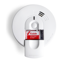
This alarm is not compatible
with Kidde CO-relays
and Strobes manufactured
before Nov. 1, 2011
PERMANENTLY
DISABLE and
DISCHARGE
ALARM
(2) Rotate slotted
arrow clockwise to
disable & discharge.
(3) Install new alarm.
(1) Push in the dashed
area with a screwdriver
to break tab.
When unit
announces
“Replace alarm”
CERTIFIED
SAFETY
SIGNALING
US
S1816
Multi-criteria Smoke Alarm
Helps Reduce
Cooking
Nuisance Alarms
UL 217 8
th
Ed.
底盘
注意“A”
标记线的方向.
LED 指示灯
按上面的图示,报警器对齐底盘“A”标记线,
安装到报警器到底盘上,顺时针旋转90度。
拆卸
安装
A
When mounting
in a hallway,
the "A" line should
be parallel with the
hallway. When wall
mounting, the "A"
line should be
horizontal.
Alignment Marks
(”A” Line) on
Mounting
Bracket
Mark and drill two 3/16" (5mm)
holes for wall anchors.
 Loading...