TECHNICAL SPECIFICATIONS
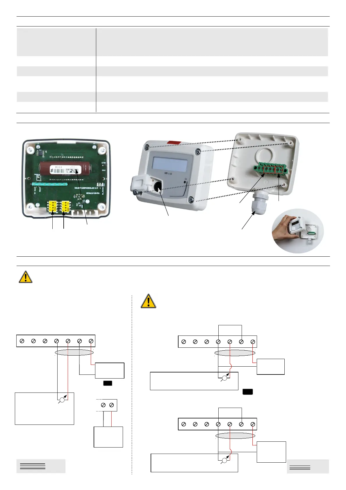
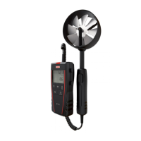
CONNECTIONS
Inactive
switch
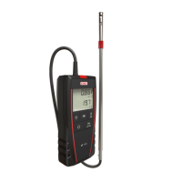
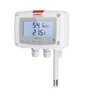
)&, - active 0-10 V (power supply 24 Vac/Vdc ± 10%), 3-4 wires
- passive loop 4-20 mA (power supply 16/30 Vdc), 2 wires
- Common mode voltage <30 VAC
- maximum load : 500 Ohms (4-20 mA) / minimum load : 1 K Ohms (0-10 V)
2 VA (0-10 V) or 0.6 VA (4-20 mA)
/1 2004/108/EC EMC ; 2006/95/EC Low Voltage ; 2011/65/EU RoHS II ; 2012/19/EU WEEE
/
Screw terminal block for cables from 0.05 to 2.5 mm
2
or from 30 to 14 AWG
Carried out according to the code of good practice.
USB-mini DIN cable
/1 Air and neutral gas
2
ELECTRICAL CONNECTIONS – as per NFC15-100 standard
Active
switch
!34!5674
V
-
+
76
L
N
Power supply
24 Vac
class II
N
L
1
2
+
5
VCO
4
GND
-
7
+
6
-
Power supply
24 Vdc
-
+
8
,
!59#,6,6
4(,,4
1
2
3
+
5
4
-
7
+
6
-
-
Power supply
24 Vdc
+
-
9,
8,
9,
+
1
2
3
+
5
4
-
7
L
6
N
-
Power supply
24 Vac
class II
L
N
9,
+
For )**+# models with +#*+: – 1-
Regulator display or
PLC/BMS
1
V
V
Regulator display or PLC/BMS 1
Regulator display or PLC/BMS 1
VCO
GND
Electrochemical
sensor
3
Power supply
terminal block
Output terminal block
LCC-S
software
connection
;05
$1
Cable gland
GND
VCO