➢ Perform the same procedure for the following figures.
➢ Press OK when the last figure is configured.
F 302 blinks, the high range is configured.
To set the low and high ranges of the channel 2, go to the folder F311 (low range) and F 312 (high range) and follow
the setting procedure of the channel 1.
To set the low and high ranges of the channel 3, go to the folder F 321 (low range) and F 322 (high range) and follow
the setting procedure of the channel 1.
6.3. Output diagnostic
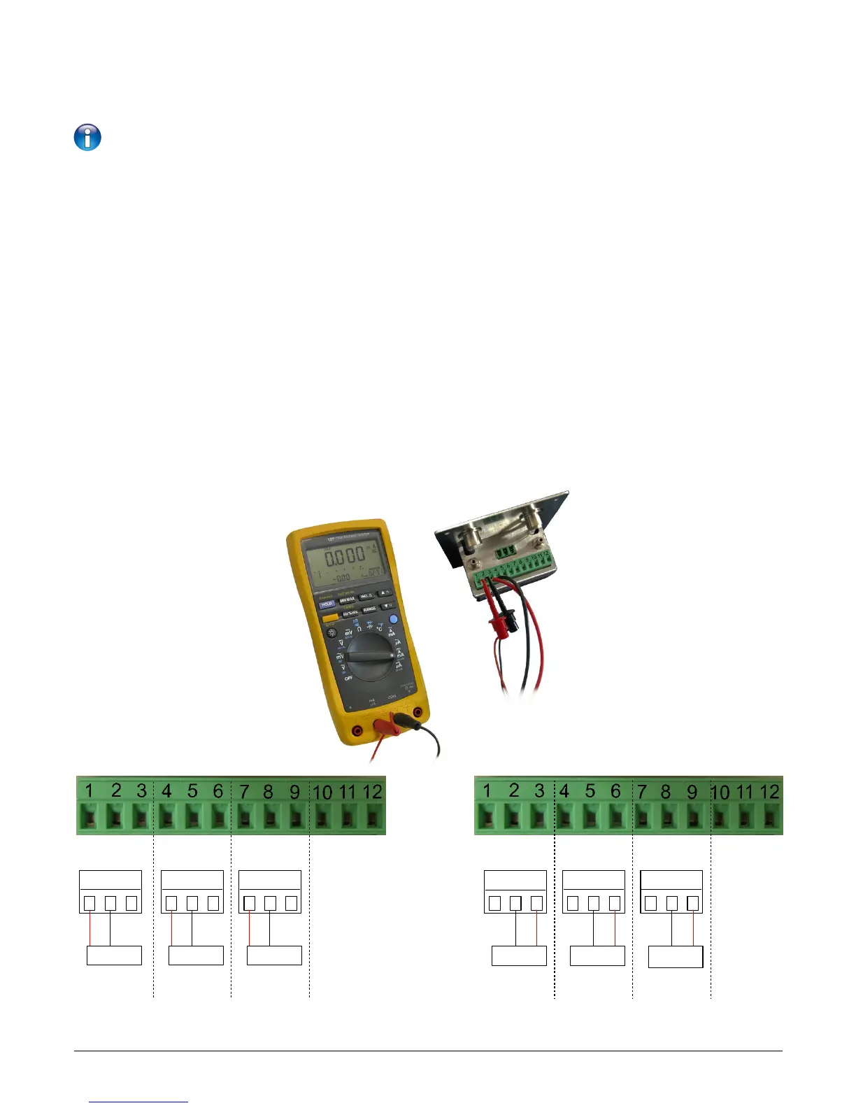
This function allows to check on a measurement device (multimeter, regulator or automate) the proper functioning of the
outputs. The transmitter will generate a voltage (between 0 and 10 V) or a current (between 0 and 20 mA) according to the
setting of the type of output.
• For a 0-10 V output signal, the transmitter will generate 0 – 5 or 10 V.
• For a 0-5 V output signal, the transmitter will generate 0 – 2.5 or 5 V.
• For a 4-20 mA output signal, the transmitter will generate 4 – 12 or 20 mA.
6.3.1 Connection configuration
Before carrying out the output diagnostics, all connections and configurations of the transmitter must be enabled, to avoid
any damage on the transmitter and the multimeter!
➢ Select an output for the output diagnostic.
OUT1, OUT2 or OUT3 indicated on the connection label.
➢ Connect a measurement device on the channel 1, 2 or 3.
F 300: Manage the analogue outputs 15
Connection of the 0/4-20 mA current output :
Connection of the 0/4-20 mA voltage output :
multimeter
-
GND
-
mA
+
1 2 3
+
V
OUT1
multimeter
7 8 9
OUT3
4 5 6
multimeter
OUT2
7 8 9
OUT3
4 5 61 2 3
multimeter
OUT1
multimeter
+
-
+
multimeter
-
GND
mA
V
GND
mA
V
GND
mA
V
GND
mA
V
GND
mA
V
OUT2
-
-
+
+
-
-
+
+
+
-
+
-
+
-
+
-