Do you have a question about the Kimo C310 and is the answer not in the manual?
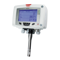
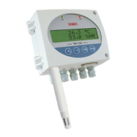
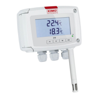
Provides an overview of the KIMO C310 multifunction transmitters and their display capabilities.
Details the function of each button on the C310 transmitter for navigation and operation.
Offers essential guidance on protecting the sensitive element of hygrometry probes from damage.
Outlines Modbus communication parameters: speed, data bits, stop bit, parity, flow control, and addressing.
Lists supported Modbus functions for register operations, including function codes and loop tests.
Explains register types, Modbus codes for alarms, values, and decimal point precision.
Steps to input the security code required to access the transmitter's configuration menu.
Covers essential transmitter settings such as screen, language, date/time, and keypad lock.
Guide to activating and assigning measurement channels to connected probes or boards.
Procedure for setting up the transmitter's analogue output signals and their ranges.
Details on activating and defining conditions for the transmitter's alarm functions.
Instructions for configuring specific probes, boards, and associated measurement parameters.
Process for enabling optional features on the transmitter using a provided activation code.
Lists Modbus registers related to device identification and basic settings like serial number and security.
Details Modbus registers for managing measurement channels, including unit selection and activation.
Modbus registers for analogue output configuration, range setting, and diagnostic functions.
Modbus registers for alarm configuration, including mode, thresholds, and audible alerts.
Modbus registers for configuring measurement integration, coefficients, offsets, and delay times.
| Measured parameters | CO, Temperature |
|---|---|
| CO measurement range | 0 to 500 ppm |
| CO resolution | 1 ppm |
| Temperature accuracy | ±0.5 °C |
| Temperature resolution | 0.1 °C |
| Protection | IP65 |
| Operating Humidity | 0 to 95% RH (non-condensing) |
| Response Time | < 30 seconds |
| Power supply | 24 V AC/DC |
| Output | 4-20 mA |