EasyManua.ls Logo

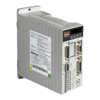
Kinco FD425-LA-000 User Manual

Kinco FD425-LA-000
206 pages
To Next Page IconTo Next Page
Page #1 background imageLoading...
Page #1 background image
Manual
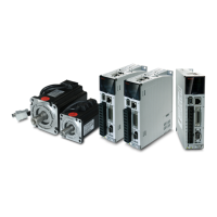
Kinco FD5 series AC servo system
Kinco Electric (shenzhen) Ltd.
www.kinco.cn

Table of Contents

Other manuals for Kinco FD425-LA-000

Question and Answer IconNeed help?

Do you have a question about the Kinco FD425-LA-000 and is the answer not in the manual?

Kinco FD425-LA-000 Specifications

General IconGeneral
ModelFD425-LA-000
TypeServo Drive
SeriesFD Series
Input Voltage220V AC
Output Current25A
Protection LevelIP20
Control ModeSpeed, Torque, Position
Communication InterfaceRS485
Power SupplySingle/Three-phase 220VAC (-15%~+10%), 50/60Hz

Summary

Chapter 1 Servo system model and configuration description

1.3 Servo drive specifications

Lists key technical specifications for the Kinco FD5 AC servo drives.

Chapter 2 Servo system installation requirements and notes

2.1 Installation of drive

Covers requirements for installing the servo drive, including mounting and clearance.

2.2 Servo motor installation

Provides installation requirements and guidance for the servo motor.

2.3.3 Precautions

Outlines crucial precautions for installation, handling, and environmental factors.

Chapter 3 Installation and wiring

3.2 External system connection

Illustrates how to connect the servo drive to the external power and control system.

3.4 External input and output connection(X1)

Explains the wiring for digital inputs and outputs on the servo drive.

Chapter 4 Controller setup with LED panel

4.1 Panel operation

Describes how to operate the controller using the front panel buttons and LED display.

4.3 Easy Use Function

Explains the simplified setup process for quickly configuring the controller for applications.

Chapter 5 KincoServo +, user guide

5.4 Read/write controller configuration

Covers reading and writing multiple controller parameters simultaneously.

5.5 Digital IO function

Explains how to configure digital inputs and outputs using the software.

5.7 Error display and error history

Explains how to display and investigate errors and error history via the software.

Chapter 6 Operation modes and control modes

6.1 General steps for starting a control mode

Outlines the general steps for setting up and starting a servo control mode.

6.2 Velocity mode (-3, 3)

Describes the two velocity modes (-3 and 3) for controlling motor speed.

6.3 Torque mode(4)

Explains how to operate the servo system in torque control mode.

6.4 Position mode(1)

Describes how to operate the servo system in position control mode.

6.5 Pulse mode (-4)

Explains how to operate the servo system using pulse inputs for velocity commands.

Chapter 7 Tuning of the servo system control

7.1 Auto-tuning

Explains the auto-tuning function for optimizing servo performance based on load inertia.

7.2 Auto-tuning test operation method

Provides methods for performing auto-tuning via the LED panel or PC software.

7.3 Manual tuning

Describes manual tuning procedures when auto-tuning is insufficient.

Chapter 8 Alarm Investigation

Alarm Investigation

Provides information on investigating and troubleshooting system alarms and errors.

Chapter 10 Communication

Appendix 1: Braking Resistor Selection

Related product manuals