EasyManua.ls Logo

Kinco FD5 Series User Manual

Kinco FD5 Series
206 pages
To Next Page IconTo Next Page
Page #1 background imageLoading...
Page #1 background image
Manual
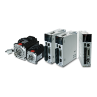
Kinco FD5 series AC servo system
Kinco Electric (shenzhen) Ltd.
www.kinco.cn

Table of Contents

Other manuals for Kinco FD5 Series

Question and Answer IconNeed help?

Do you have a question about the Kinco FD5 Series and is the answer not in the manual?

Kinco FD5 Series Specifications

General IconGeneral
SeriesFD5 Series
FeedbackIncremental encoder, Absolute encoder
Control ModePosition, Speed, Torque
CommunicationCANopen
Protection FunctionsOvervoltage, Undervoltage, Overcurrent, Overtemperature, Short circuit
Input Voltage3-phase AC 200V-240V (±10%)

Summary

Chapter 1 Servo system model and configuration description

1.1 Description of product model

Details the naming rules for Kinco FD5 servo drive models.

1.2 Drive nameplate description

Explains the information presented on the servo drive's nameplate.

1.3 Servo drive specifications

Lists the technical specifications for the Kinco FD5 servo drives.

1.5 Configuration table

Provides a table mapping servo motors to compatible drivers and communication protocols.

Chapter 2 Servo system installation requirements and notes

2.1 Installation of drive

Covers the physical installation requirements and mounting for the servo drive.

2.1.2 Installation distance and direction

Specifies the necessary clearances and mounting orientation for proper heat dissipation.

2.2 Servo motor installation

Details the procedures and requirements for installing the servo motor.

2.3.2 Environment conditions

Outlines the environmental operating and storage conditions for the servo system.

2.3.3 Precautions

Lists important safety precautions and handling guidelines for installation.

Chapter 3 Installation and wiring

3.1 Drive description

Provides a visual overview and description of the servo drive's components and ports.

3.2 External system connection

Explains how to connect the servo drive to external electrical components.

3.3 RS232 serial port

Details the wiring and pin definitions for RS232 serial communication.

3.4 External input and output connection(X1)

Describes the wiring for digital inputs and outputs on the servo drive.

3.5 Encoder input(X2)

Explains the pin definitions and connection for encoder inputs.

3.6 Power port(X3)

Details the connections for the power supply and motor phase lines.

3.7 Communication port input(X4)

Describes the pin definitions for communication ports like RS485 and CANopen.

Chapter 4 Controller setup with LED panel

4.1 Panel operation

Explains how to operate the servo drive using the front panel display and buttons.

4.2 Panel menu structure and navigation

Outlines the menu hierarchy and navigation flow on the LED panel.

4.3 Easy Use Function

Introduces a simplified setup wizard for common applications.

4.4 Jog mode(Test run)

Describes how to perform manual motor tests using the panel controls.

4.5 Error history(F007)

Explains how to access and interpret stored error codes and history.

Chapter 5 KincoServo +, user guide

5.1 Getting started

Covers initial setup steps for the KincoServo+ PC software.

5.1.3 Starting communication

Details the process of establishing communication between the PC and the servo drive.

5.3 Firmware update

Provides instructions for updating the servo drive's firmware.

5.4 Read/write controller configuration

Explains how to read and write multiple controller parameters simultaneously.

5.5 Digital IO function

Describes how to configure digital inputs and outputs using the software.

5.7 Error display and error history

Explains how to view and analyze drive errors and history through the software.

Chapter 6 Operation modes and control modes

6.1 General steps for starting a control mode

Outlines the general procedure for setting up a control mode.

6.2 DIN Speed mode

Details how to configure speed control using digital inputs.

6.3 Torque mode(4)

Explains the operation and parameters for torque control mode.

6.4 Position mode(1)

Describes the operation and parameters for position control mode.

6.4.1 DIN introduction to Location Position

Explains how to use digital inputs for defining position segments.

6.5 Pulse mode (-4)

Details the operation and configuration for pulse input control.

6.6 Full closed loop mode

Describes the setup and operation for high-precision closed-loop control.

6.7 Homing mode(6)

Explains how to configure the homing sequence for establishing a reference position.

6.8.1 Limit function

Details how to configure software and hardware limits to protect movement range.

6.8.2 Motor brake control

Explains the control mechanisms for the motor's holding brake.

6.8.2 Stop Mode Control

Describes the different methods available for stopping the motor.

Chapter 7 Tuning of the servo system control

7.1 Auto-tuning

Introduces the automatic tuning process for optimizing system performance.

7.2 Auto-tuning test operation method

Provides steps for performing and interpreting auto-tuning tests.

7.3 Manual tuning

Explains how to manually adjust control loop parameters for performance tuning.

7.3.1 Tuning of the velocity loop

Details the process and parameters for tuning the velocity control loop.

7.4 Gain switch (Pro mode)

Describes how to switch between different PI gain sets for dynamic performance adjustment.

Chapter 10 Communication

10.1 RS232 wiring

Explains the hardware and cable requirements for RS232 communication.

10.2 RS485 Communication

Covers the hardware setup and parameters for RS485 communication.

10.2.3 MODBUS RTU communication protocol

Details the MODBUS RTU protocol used for communication.

10.3 CANopen Bus communication

Explains the CANopen communication protocol and its application.

10.3.3 CANopen Bus communication settings

Describes the configuration parameters for CANopen communication.

10.3.4 Interpolation mode based on CANopen

Explains the interpolation mode for single-axis and multi-axis control over CANopen.

Related product manuals