Chapter 4 Wiring Guide of VFD
48
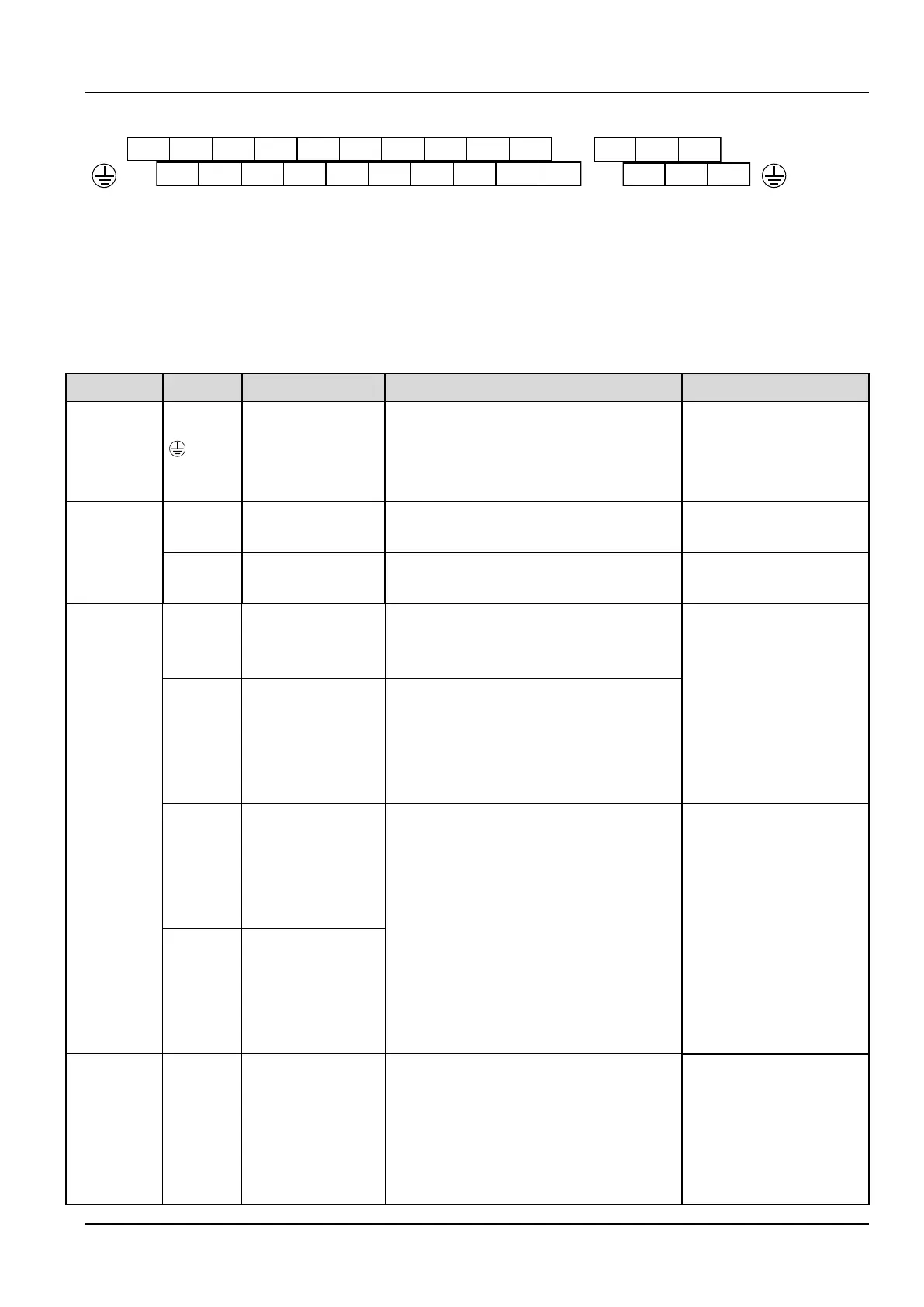
Arrangement of control circuit terminals is as follows.
AO1 AO2 AI3+ +10V 24V PLC X4 X5 X6 X7
AI1 AI2 AI3- GND X1 X2 X3 COM
485+
485-
Fig.4-2 Arrangement of control terminals
Refer to table 4-3 for description of each terminal
Table 4-3 function list of each list
PE terminal connected to shielding layer. 485
communication cable, Analog signal cable,
motor power cable shield can be connected to
this terminal here
Connected to PE terminal of
main loop inside
Provide +10V power supply
Maximum current output
is5mA
GND for analog signal and 10V power supply
Isolated from COM and
CME inside
Can accept analog voltage or current
input,jumper AI1 can select voltage or current
input mode.(Reference ground.GND)
Input voltage
range.-10V~10V(Input
impedance
45Ω)Resolution1/4000
Input current range.0mA~20
mA,
Resolution.1/2000(Need
jumper)
Can accept analog voltage or current input,
jumper AI2 can select voltage or current input
mode.(Reference ground.GND)
Analog voltage
differential input
AI3+ or analog
voltage single-ended
input
When connected to the analog voltage
differential input, AI3+ is the same-phase
input and AI3- is the inverted phase input;
when connected to the analog voltage
single-ended input, AI3+ is signal input,AI3-
should connect to GND (Reference
ground.GND)
Input voltage
range-10V~+10V(Input
resistor.15kΩ)Resolution.1/
4000
Analog voltage
differential input
AI3- or analog
voltage
single-ended input
Providing analog voltage or current output,
they are selected by the jumper AO1. The
default setting is output voltage, refer to the
function code A6.28 for detail.(Reference
ground.GND)
Voltage output
range.0V~10V
Current output
range.0/4~20mA

 Loading...
