Chapter 4 Wiring Guide of VFD
49
Providing analog voltage or current output,
they are selected by the jumper AO2. The
default setting is output voltage, refer to the
function code A6.29 for detail.(Reference
ground.GND)
Voltage output
range.0V~10VCurrent
output range.0/4~20mA
StandardRS-485communica
tion port,pleaseuse
twisted-pair cableor
shielded cable.
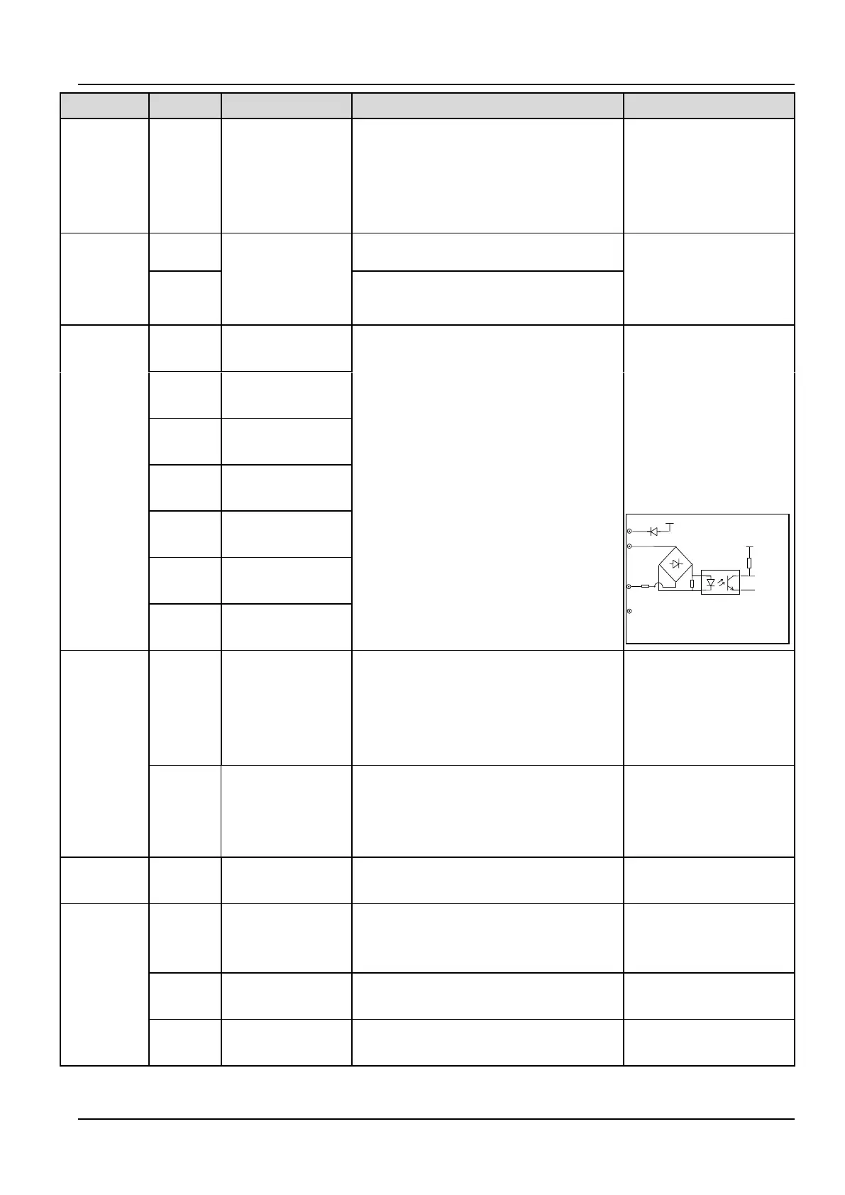
Multi-
function
input terminal
Multi-function input
terminal 1
Can be defined as multi-function digital
input terminal.(Refer to the A6 group, form
A6.00 to A6.06)
Optocoupler isolation input
Input resistor.R=3.3kΩ
Maximum frequency input
of X1~X6.200Hz
Maximum input frequency
of X7.100kHz
Input voltage range.2~30v
Multi-function input
terminal 2
Multi-function input
terminal 3
Multi-function input
terminal 4
Multi-function
input terminal 5
Multi-function
input terminal 6
Multi-function
input terminal 7
Multi-
function
output
terminal
Bi-direction
open-collector output
Can be defined as multi-function digital
output terminal , refer to the A6.14 for detail
(Com port.CME)
Optocoupler isolation
outputMaximum working
voltage.30vMaximum
output current.50mA
Opencollector pulse
terminal
Can be defined as multi-function pulse signal
output terminal , refer to the A6.25 for
detail(Com port.CME)
Maximum output
frequency.100kHz(Depend
on the A6.26)
Providing +24V power for others
Maximumoutputcurrent.200
mA
Common port of
multi-function input
Common port of Multi-function input
(Short cut with 24V in default)
Common port of X1~X7,
PLC is isolated from 24V
internally
Common port of
24V power supply
Three common ports in all, cooperate with
other terminals
COM is isolated from CME
and GND inside the drive
Common port of multi-function output
terminal Y1

 Loading...
