Low Speed operation with Constant Torque
Driving a common motor at low speed for a long
time, the drive’s rated output torque will be reduced
considering the deterioration of heat dissipation
effect, so a special variable frequency motor is
needed if operation at low speed with constant
torque for a long term.
Motor’s over-temperature protecting threshold
When the motor and driver are matched, the drive
can protect the motor from over-temperature. If the
rated capacity of the driven motor is not in
compliance with the drive, be sure to adjust the
protective threshold or take other protective
measures so that the motor is properly protected.
Operation above 50Hz
When running the motor above 50Hz, there will be
increase in vibration and noise. The rate at which
the torque is available from the motor is inversely
proportional to its increase in running speed.
Ensure that the motor can still provide sufficient
torque to the load.
Lubrication of mechanical devices
Over time, the lubricants in mechanical devices,
such as gear box, geared motor, etc. when running
at low speed, will deteriorate. Frequent
maintenance is recommended.
Braking Torque
Braking torque is developed in the machine when
the drive is hoisting a load down. The drive will trip
when it can not cope with dissipating the
regenerative energy of the load. Therefore, a
braking unit with proper parameters setting in the
drive is required.
The mechanical resonance point of load
The drive system may encounter mechanical
resonance with the load when operating within
certain band of output frequency. Skip frequencies
have been set to avoid it.
Start and stop frequently
The drive should be started and stopped via its
control terminals. It is prohibited to start and stop
the drive directly through input line contactors,
which may damage the drive with frequent
operations.
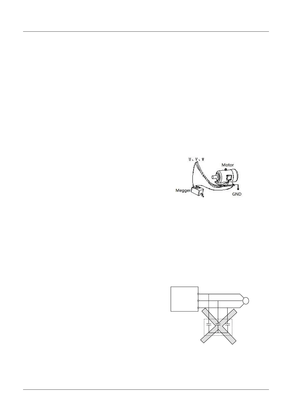
Insulation of Motors
Before using the drive, the insulation of the motors
must be checked, especially, if it is used for the first
time or if it has been stored for a long time. This is to
reduce the risk of the Drive from being damaged by
the poor insulation of the motor. Wiring diagram is
shown in Fig. 1-1. Please use 500V insulation tester
to measure the insulating resistance. It should not
be less than 5MΩ.
Fig. 1-1 checking the insulation of motor
1.3.2 About Variable Frequency Drive
Varistors or Capacitors Used to Improve the Power
Factor
Considering the drive output PWM pulse wave,
please don't connect any varistor or capacitor to the
output terminals of the drive, otherwise tripping or
damaging of components may occur; as shown in
fig 1.2
 Loading...


