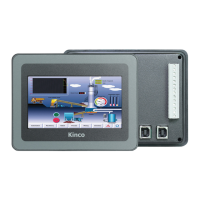
Kinco-HP
User Manual
1.4.4 Dimension
Chapter 2 PLC Introduction
2.1 Functions
2.1.1 CPU Status and LEDs
The CPU has two modes: STOP mode and RUN mode.
In RUN mode, the CPU executes the main scan cycle and all interrupt tasks.In STOP mode,
the CPU only process communication requests which comes from KincoBuilder software and
other Modbus RTU master device.At the same time, all output points are immediately output
to the "stop output" value defined in [Hardware Configuration] of the user project.
Change CPU status
HMI-PLC provides one way for manually changing the CPU status: Executing [RUN] or
[STOP] in Kincobuilder.
Usually when the PLC is power on, default status of PLC is RUN status.
Below situation, the PLC status depend on Kincobuilder programming
a— PLC RUN mistake (strong mistake) will stop the PLC
b— The user use Kincobuilder [setup], PLC is RUN/STOP status
c— Users use STOP instruction to stop PLC
d— If downloading project failed, PLC will keep STOP status.

 Loading...