2M1180N/2M2280N Stepper Motor Driver
9
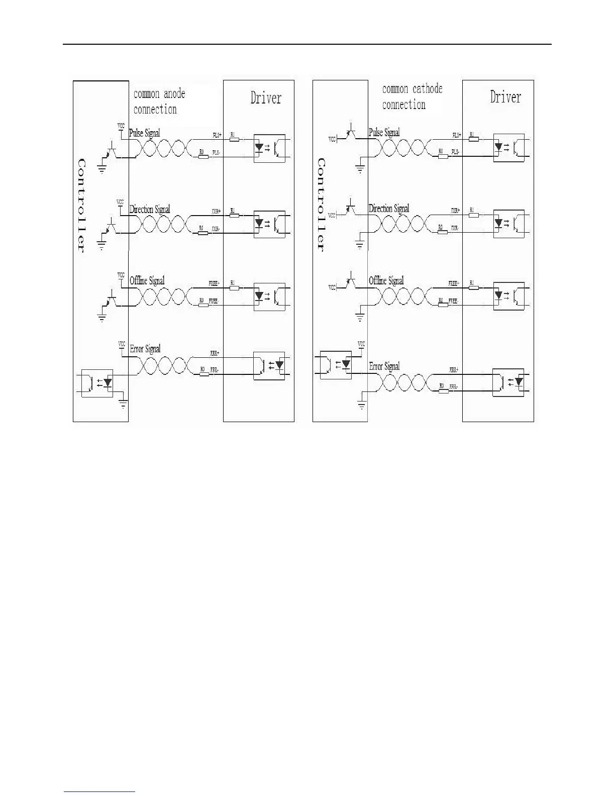
Twisted-pair Way Control Signal Wiring Diagram
The input circuits of all control signals of the driver have been reliably isolated
through optocoupler elements, which minimize the interference from external
electrical noises.
In the figure, R0 is an external current limit resistor used to curb the input
si
gnal
current of the driver. When control signal is at 24VDC, a 2K resistor can be connected;
when the control signal is at 12VDC, a 1K resistor can be connected. The current at
the input port of the driver must be within 6~16 mA; otherwise, the current too less
may cause signal loss,much more current will damage the equipment.
ERR signal is open collector output and requires an external power supply.
The
maximum external voltage cannot exceed 30V. Never connect the ERR signal port in
reversed polarity; otherwise, it may cause damage to the port.
if driver work in a strong interference field,the control signal wiring is recommended
twisted-pair way,this can reduce the interference signal source interfere control
signal.
 Loading...