EasyManuals Logo

Kinco N Series User Manual

Kinco N Series
36 pages
To Next Page IconTo Next Page
To Previous Page IconTo Previous Page
Page #27 background imageLoading...
Page #27 background image
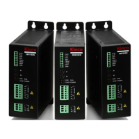
2M1180N/2M2280N Stepper Motor Driver
11
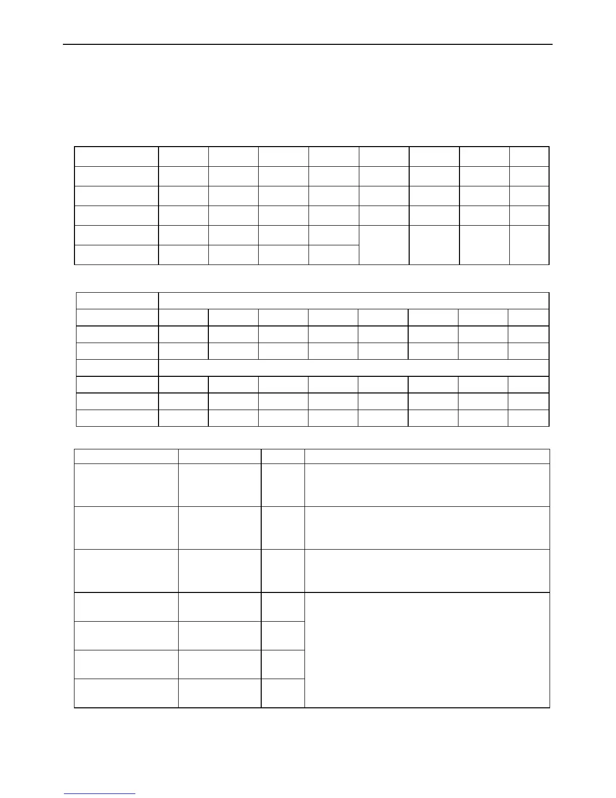
3.5 DIP Switch Settings
The driver is configured with two round DIP switches S1 and S2, which are used for
macro-step value selection, current value selection, test running status enabling, and
PLS+DIR or CW/CCW control signal selection.
S1,Micro-step:
S1
0
1
2
3
4
5
6
7
Micro step
2
4
5
8
10
16
20
3
2
Pulse/rev
400
800
1000
1600
2000
3200
4000
6400
S1
8
9
A
B
C
D
E
F
Micro step
50
64
100
128
NA
NA
TEST
NA
Pulse/rev
10000
12800
20000
25600
S2, Current:
Mode
PLS+DI
R
S2
0
1
2
3
4
5
6
7
Rms(A)
3.18
3.54
3.89
4.24
4.60
4.95
5.30
5.65
Peak(A)
4.5
5
5.5
6
6.5
7
7.5
8
Mode
CW/CCW
S2
8
9
A
B
C
D
E
F
Rms(A)
5.65
5.30
4.95
4.60
4.24
3.89
3.54
3.18
Peak(A)
8
7.5
7
6.5
6
5.5
5
4.5
Mode select::
Mode
S1
S2
operation
Test running
E
0~F
When driver power off, set S1 on E,S2
among 0~F, motor will run at 60rpm after
power on.
PLS+DIR
0~B
0~7
When driver power off, set S1 among
0~B, S2 among 0~7, driver will run at
PLS+DIR mode after power on.
CW/CCW
0~B
8~F
When driver power off, set S1 among
0~B, S2 among 8~F, driver will run at
CW/CCW mode after power on.
Enable auto
half current
F
C
When driver power off, set S1 and S2 to
select mode, then power on driver, the
LED statue: RUN LED Blink, POWER LED
on, ERR LED on, CHOP LED off, this mean
mode have setted. After power off, set
micro step and phase current as normal
use.
Disable auto
half current
F
D
Enable step
smoothing filter
F
F
Disable step
smoothing filter
F
E

Questions and Answers:

Question and Answer IconNeed help?

Do you have a question about the Kinco N Series and is the answer not in the manual?

Kinco N Series Specifications

General IconGeneral
BrandKinco
ModelN Series
CategoryControl Unit
LanguageEnglish

Related product manuals