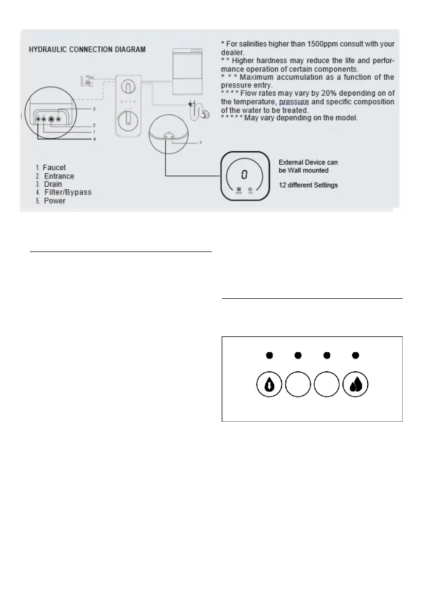
* For salinities higher than 1500ppm consult with your
dealer.
* Higher hardnesses may reduce the life and perfor-
mance operation of certain components.
** Maximum accumulation as a function of the pres-
sure entry.
**** Flow rates may vary by 20% depending on of the
temperature, pressure and specific composition of
the water to be treated.
1
2
3
4 ***** May vary depending on the model.
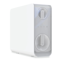
1.
Faucet
External Device can be Wall
2.
Entrance
mounted
3.
Drain
4.
Filter/Bypass
12 different
Settings
MODE TDS
5.
Power
2.
OPERATION
OF
THE
EQUIPMENT
user that adequate maintenance must be carried out to
guarantee the quality of the water dispensed.
•
The mains water to be treated enters the equipment
through the pre-filtration stage that incorporates a
GAC (CF) turbidity and carbon filter. In this filtration
stage, suspended particles, chlorine, its derivatives and
other organic substances are retained.
3.
INTERFACE.
SYSTEM
STATE
•
The passage of water into the equipment is controlled
by a cut-off solenoid valve (Si).
•
The water, after being treated in the filtration stage, is
driven towards the reverse osmosis (MRO) membrane.
The equipment incorporates a pump (P) to increase the
pressure. The pressure of the water on the membrane
makes the reverse osmosis process possible.
•
Before leaving the System, the water passes through
the carbon post-filter (part of MRO), which improves
the taste.
•
Reject water or water with excess salts and other dis-
solved substances is directed to the drain for disposal.
•
Direct flow equipment controls start and stop by
means of a pressure switch (HPS).
•
The equipment incorporates different functional and
/ or security systems, managed by a state-of-the-art
electronic module:
•
Electronic leak detection system (L). When the system
detects this situation, it blocks the equipment by emi-
tting an acoustic and light signal alarm. The equipment
will remain blocked until the detection probe is dry.
•
Probe for reading the conductivity of the produced
water to evaluate the state of the membrane and its
components (Q). When dispensing water from the tap,
the system will measure the conductivity of the produ-
ced water.
Display:
1.
Working indicator
2.
CF filter life indicator/pusher
3.
RO membrane filter life indicator/pusher
4.
Failure / quality water indicator
3.1.
COLORS OF THE WATER QUALITY INDICATOR
Blue: TDS≤200ppm*
Purple: 200ppm <TDS ≤ 300ppm*
Red: TDS> 300ppm*
*Linked to the selected Program
3.2.
OPERATION INDICATOR
It will remain illuminated in blue while the equipment is
dispensing water.