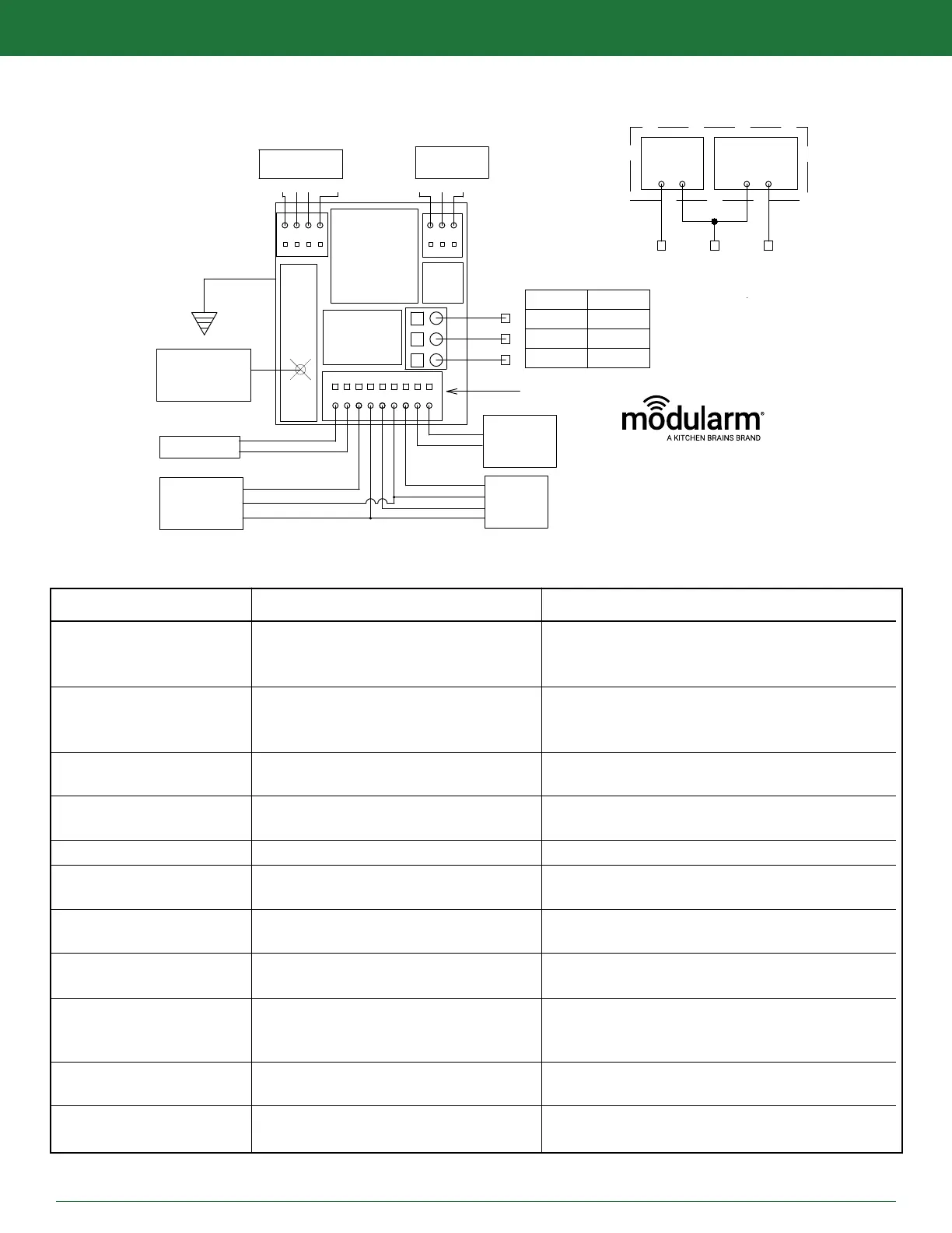
EXPANSION
PORT
TXRX SHLD
DRY
CONTACTS
C NC NO
SUPPLY
POWER
120 VAC
LIGHTS
N/C
CONTACTS
TEMP.
PROBE
MD-1
MOTION
DECTECTOR
IP-1
PUSH
BUTTON
9V,NI-MH
RECHARGEABLE
BATTERY
MAGNETIC
*COLORS INDICATED ARE TYPICAL
BLOCK
LINE VOLTAGE CONNECTIONS
TEMP B R Y DOOR
MD
W
G
B
R
(GREEN)
B
W
R
Y
1000W
8.3A@120VAC
*75LC MUST
BE GROUNDED
GREEN WIRE
75LC TERMINAL
PR
MODULARM 75LC WIRING DIAGRAM
75LC
FROM
BACK
C
B
A
VERSION 1
VERSION 2
LINE
LINE
NEUTRAL
NEUTRAL
LIGHTS
LIGHTS
LINE
NEUTRAL
LIGHTS
SALES@KITCHENBRAINS.COM
MODULARM
WWW.KITCHENBRAINS.COM
MODULARM
®
75LC MULTI-MONITOR | OPERATING MANUAL
MODULARM 75LC WIRING DIAGRAM REV 3
MESSAGE DISPLAYED POSSIBLE CAUSE CORRECTIVE ACTION
HI + ## + (AL) Temperature above HIGH set point for
less time than alarm delay (AL indicates
indicates longer than time delay)
Lo + ## + (AL) Temperature below LOW set point for
less time than alarm delay (AL indicates
longer than time delay)
LO+OPN Open circuit or out of range value on
temp probe
HI+ SHR Short circuit or out of range value on
temp probe
HI+ SHR LO+OPN Door sensor & temp probe are reversed
OCC Occupancy sensor is giving error
PF Line voltage is not detected
HLP (cannot silence) Fault from IP-1
ERR + ## Fault from I-BOARD or 75LC WIRELESS
DOR (cannot silence) Fault on door contact
Rapidly Changing Empty compartment, poor sensor
Temperature location, or wrong sensor
Wait for defrost cycle to end, check HIGH set point
(& alarm delay), possibly adjust setting, check
location of temp probe and relocate if necessary
Check location of temp probe, check LOW set point
(& alarm delay) & possibly adjust setting.
Relocate if necessary
Ensure proper electrical connection of temp probe,
ensure proper sensing bulb and inspect run of wire
Ensure proper electrical connection of temp probe,
ensure proper sensing bulb and inspect run of wire
Door sensor & temp probe are reversed
Check connection to Motion Detector and Motion
detector device
Check Line voltage, check for signs of
physical damage
Inspect wire connection points [B W R Y] on 75LC
and IP-1
Inspect wire connection points on 75LC [TX RX
SHLD PR] and Crossover device (I-BOARD or
75LC WIRELESS
Inspect wire connection points and physical
contact alignment
Fill compartment, relocate sensor and call for
assistance in identication
This document contains confidential information. Dissemination, publication, copying, or duplication of this document or software described herein without prior written authorization is strictly prohibited.
Page 21 of 24
kitchenbrains.com
1-800-327-8766
TROUBLESHOOTING GUIDE