5-1
COMPONENT TESTING
Before testing any of the components, perform
the following checks:
The most common cause for control failure
is corrosion on connectors. Therefore, dis-
connecting
and reconnecting wires will be
necessary throughout test procedures.
All
tests/checks should be made with a
VOM or DVM having a sensitivity of 20,000
ohms-per-volt DC, or greater.
•
•
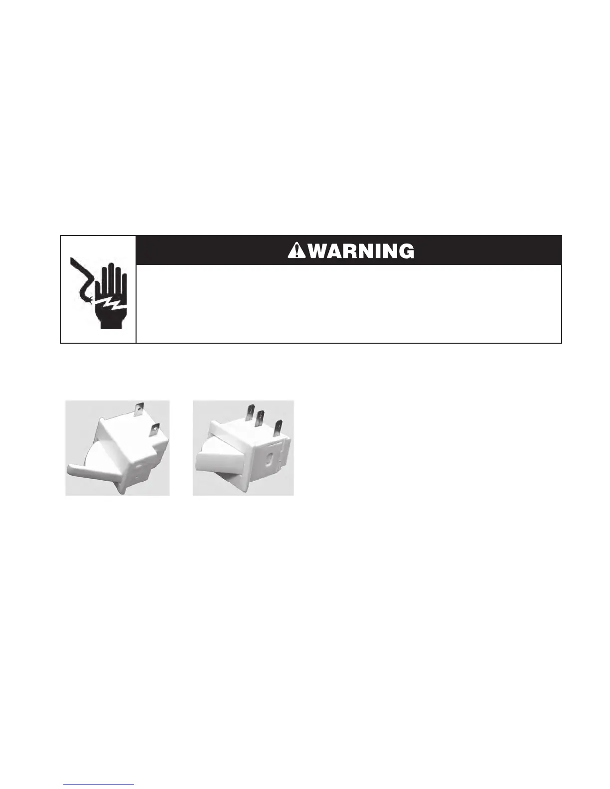
4. R
efrigerator Door Switch: Touch the
ohmmeter test leads to the C and NC
door switch terminals. The meter should
indicate a closed circuit (0 Ω). Press the
a
ctuator arm and the meter should indicate
an open circuit (infinite).
5. Freezer
Door Switch: Touch the ohm-
meter test leads to the indicated terminals.
The meter should indicate as follows:
a)
C and NC = closed circuit (0 Ω).
b) C and NO = open circuit (infinite)
c) Press the actuator arm and the meter
indications in steps 5a and 5b should
change states.
REFRIGERATOR & FREEZER
DOOR SWITCHES
Check all connections before replacing
components, looking for broken or loose
wires, failed terminals, or wires not pressed
into connectors far enough.
Resistance
checks must be made with
power cord unplugged from outlet, and
with wiring harness or connectors discon-
nected.
•
•
Electrical Shock Hazard
Disconnect power before servicing.
Replace all parts and panels before operating.
Failure to do so can result in death or electrical shock.
Refrigerator
Door Switch
Freezer
Door Switch
C
NC
NC
NO
C
Refer to pages 4-2 or 4-10 for the procedures
for accessing the refrigerator and freezer door
switches.
1
. Unplug refrigerator or disconnect power.
2. Disconnect the wires from the door switch
terminals.
3.
Set the ohmmeter to the R x 1 scale.