5-5
Electrical Shock Hazard
Disconnect power before servicing.
Replace all panels before operating.
Failure to do so can result in death or electrical shock.
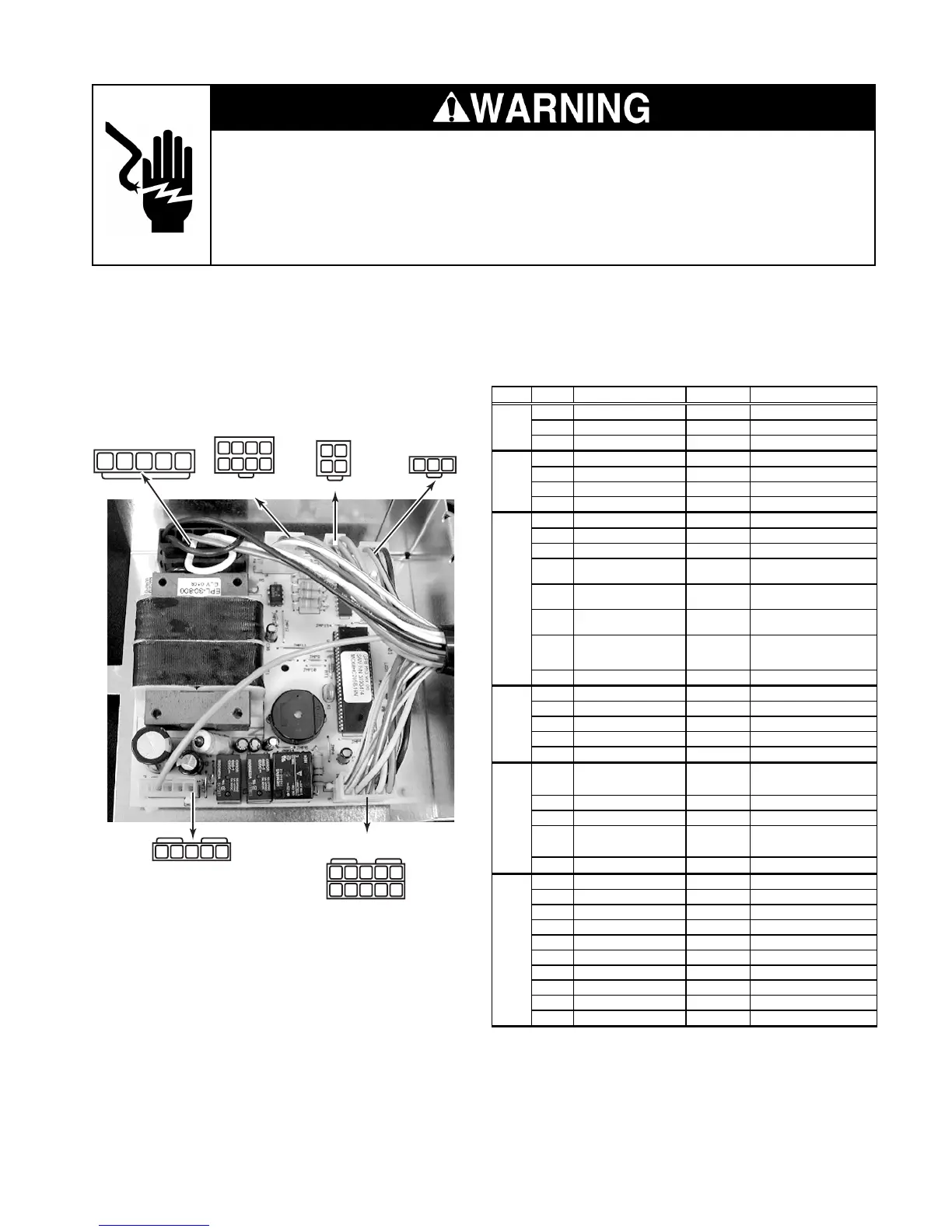
MAIN CONTROL BOARD
Refer to page 4-18 for the procedure for servicing the main control board.
NOTE: See the chart for the main control board test specifications.
INPUTS
P4
THERMISTORS
P3
DISPLAY BOARD
P2
120 VAC SUPPLY
P5
P6
P7
OUTPUTS
1
1
2
12
3
123
4
34
5678
2345
1
2
345
1
2
345
109876
PLUG PIN # DESCRIPTION
OUTPUT
CONDITION
1 Communication Line N / A
2 Display Voltage 12 VDC
Measured at pins 2 & 3
3 GND GND
1 Ref. Thermistor GND
2 Frz. Thermistor GND
3 Ref. Thermistor Output 5 VDC
Measured at pins 1 & 3
4 Frz. Thermistor Output 5 VDC Measured at pins 2 & 4
1 N/A
2 N/A
3 N/A
4 Ref. Door Input 120 VAC
Voltage present when door
is o
en
5 Ice Maker Valve Input 120 VAC
Voltage present when ice
maker is ener
ized
6 Dispenser Valve Input 120 VAC
Voltage present when
dis
enser valve is ener
ized
7 Bimetal Input 120 VAC
Voltage present when
bimetal is closed
8 N/A
1 AC GND AC GND
2 AC L1 120 VAC
3 AC Neutral AC Neutral
4 AC Neutral AC Neutral
5 AC L1 120 VAC
1 Condenser Fan 120 VAC
Voltage present when
condenser fan is on
2 N/A
3 N/A
4 Defrost Heater 120 VAC
Voltage present when
defrost heater is on
5 N/A
1 Air Door
2 Air Door
3 Compressor Drive 3 - 6 VDC
Measured at pins 3 & 8
4 Evap. Fan Feedback N / A
5 Evap. Fan Constant 12 VDC
Measured at pins 5 & 9
6 Air Door
7 Air Door
8 Compressor Drive 3 - 6 VDC
Measured at pins 3 & 8
9 Evap. Fan Ground Evap. GND
10 Evap. Fan Run Voltage 5 - 12 VDC Measured at pins 9 & 10
P6
P7
P2
P3
P4
P5