10 11
ENGLISH
OPERATING INSTRUCTIONS
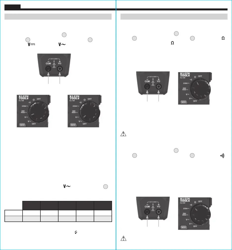
AC/DC VOLTAGE (LESS THAN 600V)
1. Insert RED test lead into VΩ jack
5
, and BLACK test lead into
COM jack
4
, and rotate function selector switch
2
to the
DC Voltage
or AC Voltage setting. Note "DC" or "AC"
on the display.
2. Apply test leads to the circuit to be tested to measure voltage.
The meter will auto-range to display the measurement in the
most appropriate range.
NOTE: If "–" appears on the LCD, the test leads are being applied to
the circuit in reverse. Swap the position of the leads to correct this.
NOTE: When in a voltage setting and the test leads are open,
readings of order mV may appear on the display. This is noise and
is normal. By touching the test leads together to close the circuit
the meter will measure zero volts.
NOTE: To access mV range for V AC
the "RANGE" button
7
must be used.
NOTE: When voltages in excess of 25V AC or 60V DC are
measured, the Hazardous Voltage Indicator
will appear on the
display.
OR
Red leadBlack lead
Manual Mode Sequence
First
Press
Second
Press
Third
Press
Fourth
Press
Fifth
Press
AC Range 0-600V 0-200V 0-20V 0-2V 0-200mV
DC Range 0-20V 0-2V 0-200mV 0-600V 0-200V
OPERATING INSTRUCTIONS
RESISTANCE MEASUREMENTS
1. Insert RED test lead into VΩ jack
5
, and BLACK test lead into COM
jack
4
, and rotate function selector switch
2
to the Resistance
setting. The resistance symbol will appear on the display.
2. Remove power from circuit.
3. Measure resistance by connecting test leads to circuit. The
meter will auto-range to display the measurement in the most
appropriate range.
NOTE: When in a Resistance setting and the test leads are open
(not connected across a resistor), or when a failed resistor is under
test, the display will indicate O.L. This is normal.
DO NOT attempt to measure resistance on a live circuit.
CONTINUITY
1. Insert RED test lead into VΩ jack
5
and BLACK test lead into COM
jack
4
, and rotate function selector switch
2
to the Continuity
setting.
2. Remove power from circuit.
3. Test for continuity by connecting conductor or circuit with test
leads. If resistance is measured less than 10Ω, an audible signal
will sound and display will show a resistance value indicating
continuity. If circuit is open, display will show "OL".
DO NOT attempt to measure continuity on a live circuit.
Red leadBlack lead
Red leadBlack lead