DIVA SLIM PELLET BOILER STOVE
23
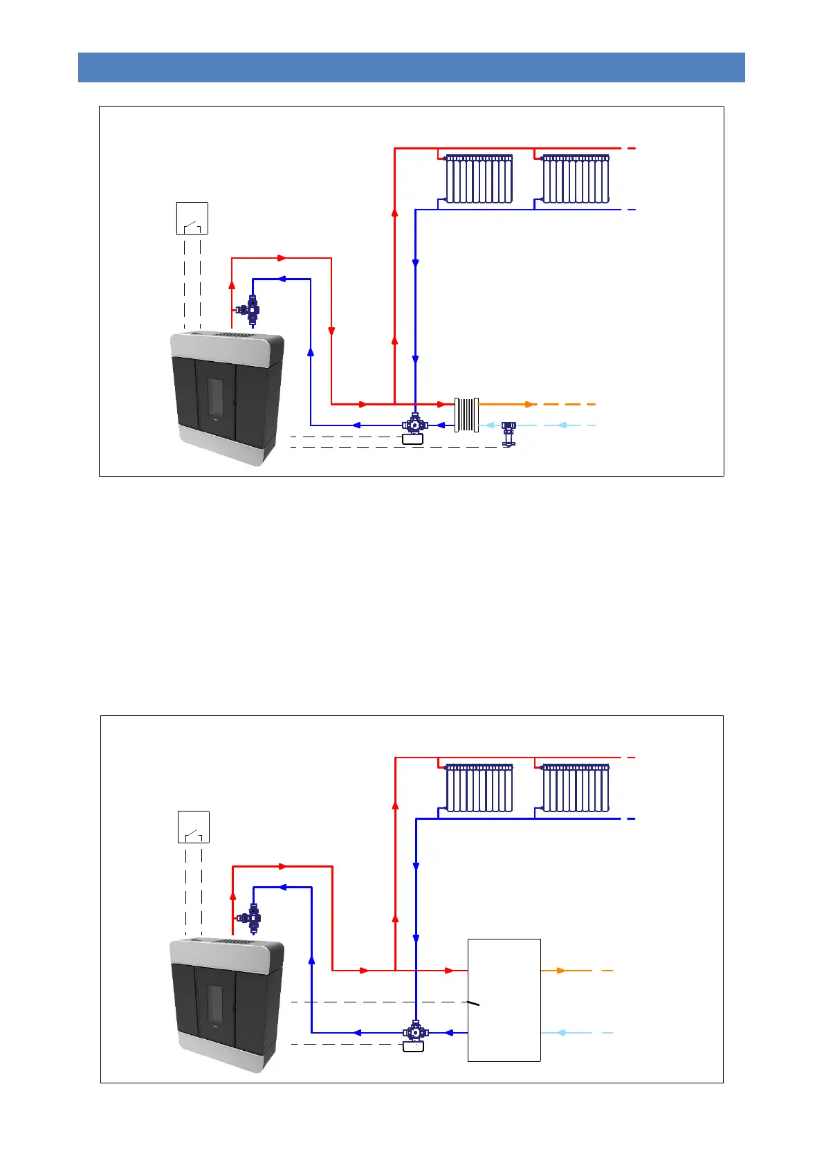
Plumbing layout 1 involves connecting the boiler stove to a heating system (or centralised puffer) managed by one or
more room thermostats. These are connected to the terminal located inside the appliance’s left technical compartment.
DHW generation, where required, will be obtained through a plate heat exchanger fitted outside of the boiler stove and
controlled by a flow switch, which is also connected to a terminal on the boiler stove. This function of this switch is to
bring the appliance immediately to the DHW output working mode and to switch a three-way motor-driven valve to give it
priority.
PLUMBING LAYOUT “2” – Not used
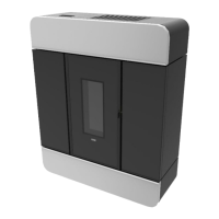
PLUMBING LAYOUT “3” – Boiler stove connected to a heating system and a DHW cylinder.
Bollitore
accumulo
ACS
T.A.
A
B
AB